
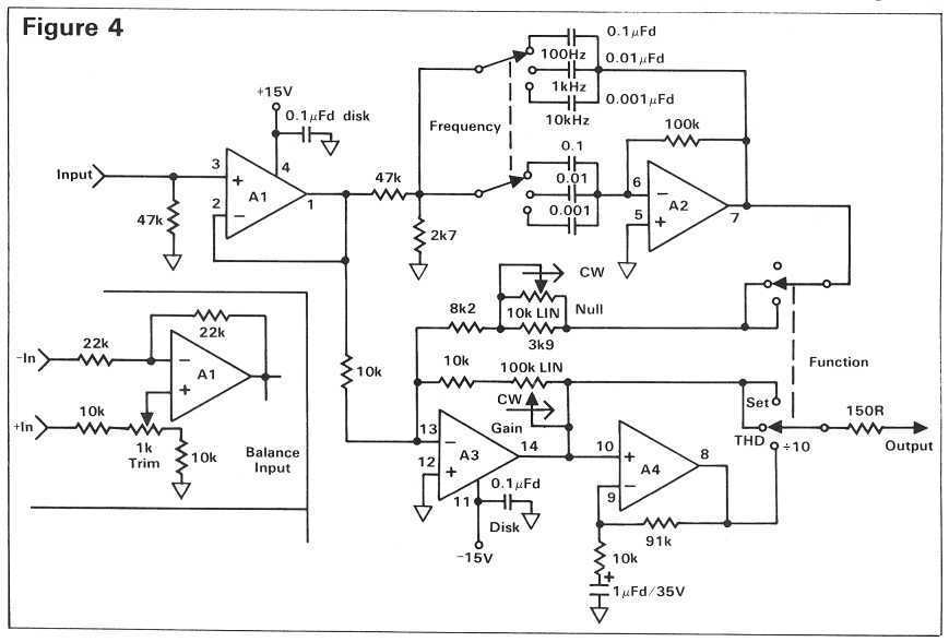
Wien-Bridge-Based Oscillator With Very Low Distortion

The oscillator circuit described is a sophisticated design that enhances the performance of the traditional Wien bridge oscillator by employing modern electronic components. The use of a photocell allows for light-dependent modulation of the circuit's output, which contributes to its stability and accuracy. The common-mode suppression circuit plays a crucial role in minimizing noise and interference, ensuring that the output signal remains clean and precise.
In this configuration, the traditional lamp, which is typically used in Wien bridge oscillators to provide feedback and stabilize the amplitude of oscillation, has been replaced with an electronic component. This substitution not only improves reliability by eliminating mechanical wear associated with lamps but also increases the overall efficiency of the oscillator. The electronic equivalent can be finely tuned to optimize performance, leading to a significant reduction in distortion levels to as low as 0.0003%.
The oscillator operates by generating a sine wave output, which is essential in various applications such as signal processing, audio synthesis, and telecommunications. The photocell's responsiveness to ambient light levels allows for dynamic adjustments in the oscillator's frequency and amplitude, making it suitable for environments where conditions may change.
Overall, this advanced oscillator circuit represents a significant evolution in oscillator technology, combining innovative components and design techniques to achieve superior performance metrics. This complex oscillator circuit uses a photocell and common-mode-suppression circuitr y to achieve distortion of 0.0003%. This oscillator circuit replaces the lamp in the traditional Wien bridge with an electronic equivalent. 🔗 External reference
Related Circuits
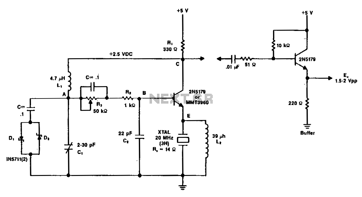
A typical circuit operating at 20 MHz is illustrated. The crystal, featuring an internal series resistance (Rs) of 14 ohms, oscillates at its third harmonic frequency. Diode clamps D1 and D2 ensure constant amplitude control. The transistor functions continuously...
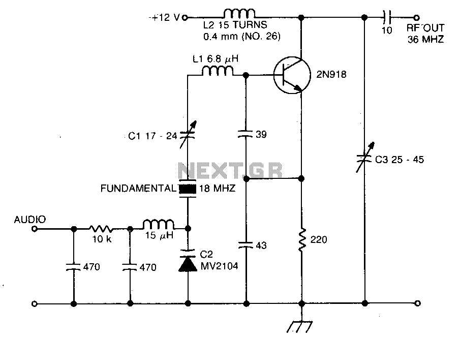
The crystal operates into a complex load at series resonance. L1, C1, and C2 balance the crystal at zero reactance. Capacitor C1 fine-tunes the center frequency. A tank circuit consisting of L2 and C3 doubles the output frequency, allowing...
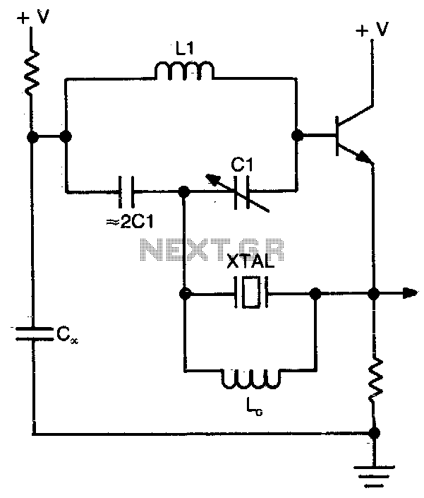
This circuit operates at or near series resonance. It is a well-designed circuit with no parasitics. It is easy to tune and has good frequency stability. The circuit in question utilizes series resonance to achieve optimal performance. At series resonance,...
A question about electronics involves a project to create a simple circuit that causes an LED to flash. To design a circuit that makes an LED flash, a basic understanding of electronic components and their configurations is essential. The simplest...

Any standard oscillator, such as a Colpitts or Hartley configuration, can be utilized to generate the local oscillator (LO) frequency required by the NE602. The NE602 is a versatile integrated circuit commonly used in radio frequency applications, particularly in mixer...
The pre-distortion circuit described here is extremely simple and only requires one trimmer adjustment, though you will need an accurate way to measure THD in order to achieve the best results. A dedicated distortion analyzer to help you adjust...
Warning: include(partials/cookie-banner.php): Failed to open stream: Permission denied in /var/www/html/nextgr/view-circuit.php on line 713
Warning: include(): Failed opening 'partials/cookie-banner.php' for inclusion (include_path='.:/usr/share/php') in /var/www/html/nextgr/view-circuit.php on line 713