
DIY Audio Function Generator Part 1
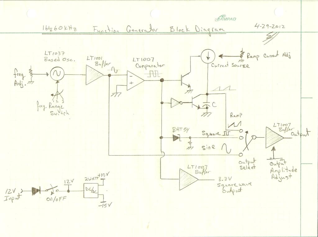
The project described appears to focus on creating electronic circuits that can be completed within a few hours, emphasizing practical learning and enjoyment in the process of building. Such projects typically involve basic components such as resistors, capacitors, transistors, and microcontrollers.
To create a more substantial project, one could consider developing a simple microcontroller-based system, such as a temperature monitoring device. This project could utilize an Arduino or a similar microcontroller platform, which is ideal for rapid prototyping and learning.
The schematic for this temperature monitoring device would include the following components:
1. **Microcontroller**: An Arduino Uno or Nano, which serves as the central processing unit for the project.
2. **Temperature Sensor**: A digital sensor like the DS18B20 or an analog sensor like the LM35, which will measure the ambient temperature.
3. **Power Supply**: A USB power source or a battery pack to provide the necessary voltage to the microcontroller and sensors.
4. **Display Module**: An LCD or OLED display can be integrated to visualize the temperature readings.
5. **Resistors and Capacitors**: These passive components may be used for pull-up or pull-down configurations, as well as for noise filtering in the circuit.
6. **Breadboard or PCB**: For prototyping, a breadboard can be used to connect all components without soldering. For a more permanent solution, a printed circuit board (PCB) can be designed.
The circuit connections would involve linking the temperature sensor to the appropriate pins on the microcontroller, ensuring that any necessary resistors are placed in accordance with the sensor's specifications. The display module would also be connected to the microcontroller, allowing it to output the temperature readings for user visibility.
Programming the microcontroller would involve writing a simple code that initializes the sensor, reads the temperature data, and then outputs this data to the display at regular intervals. This project not only serves as a practical application of electronics principles but also enhances programming skills through the integration of hardware and software.
Overall, this type of project provides a foundation for more complex systems and can be expanded with additional features such as data logging, wireless communication, or integration with IoT platforms for remote monitoring.Most of my Blog posts involve short 3-4 hour projects/hacks that I just build up for learning and fun. I thought it was time to develop something a bit mo.. 🔗 External reference
Related Circuits
This signal generator uses a three channel DAC to generate Composite video signal (CVBS) and S video signal (Y/C separated) at the same time, left one channel is not used in NTSC format. It is assigned for one of...
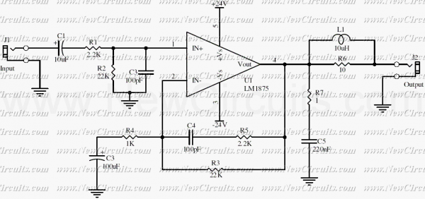
This simple 20 watts audio power amplifier is designed for home-brewed purpose. The L1 should be able to handle a current up to 4A to drive speaker in full load. The distortion is 0.015% @ 1KHz / 20W. This...
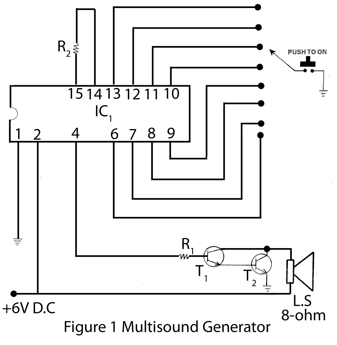
The multisound generator is an intriguing project within the alarm system series. This generator produces eight different types of sounds, and it includes a circuit diagram for various electronic projects. The multisound generator circuit is designed to create a variety...
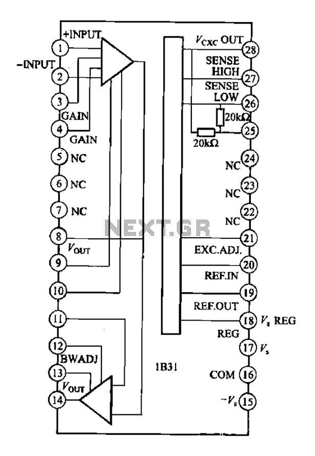
The Analog Devices 1831 is designed for strain gauge signal conditioning applications. It features an internal low drift input of 0.25V with a gain of 1000, exhibiting excellent linearity with a maximum deviation of 0.005%. The IC operates with...
Various sawtooth voltage generators utilize the principle of capacitor charging and discharging to produce sawtooth waveforms in both forward and reverse directions. A simple sawtooth voltage generator circuit is straightforward in design; however, it suffers from poor linearity in...
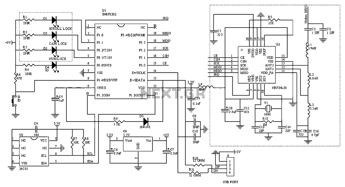
The circuit diagram for the receiving portion of a 2.4 GHz wireless keyboard is presented below. The 2.4 GHz wireless keyboard receiving circuit typically consists of several key components that work together to receive and process signals transmitted from the...