
DIY Digital Thermometer

This digital thermometer circuit employs a straightforward design, utilizing a combination of operational amplifiers and transistors to achieve accurate temperature readings. The primary sensing element is the NPN transistor BC108, which utilizes its base-emitter junction to measure temperature variations. The operational amplifier IC741 functions as a current source, ensuring that the transistor operates within its optimal range, thereby enhancing measurement accuracy.
The circuit's design allows for the use of a silicon diode as an alternative sensor, which can be beneficial in specific applications where a diode's thermal response may be preferred. The voltage change across the base-emitter junction, which is sensitive to temperature fluctuations, is amplified by a second operational amplifier (IC4). This amplification is crucial for translating small voltage variations into readable measurements on the voltmeter.
Calibration is essential for ensuring the accuracy of the thermometer. The presets VR1 and VR2 allow for fine-tuning of the zero reading and the measurement range, respectively, ensuring that the device can be adapted to different measurement scenarios. The power supply for the operational amplifiers is derived from a combination of a positive voltage regulator (IC7805) and a negative low-dropout regulator (IC7660), providing a stable ±5V supply necessary for optimal operational amplifier functionality.
The choice of a 9V battery as the power source ensures portability and ease of use, making this thermometer suitable for various applications, from laboratory settings to field measurements. The recommendation to assemble the circuit on a general-purpose PCB and enclose it in a plastic box emphasizes the importance of protecting the components from environmental factors and mechanical damage. Overall, this digital thermometer circuit exemplifies an efficient and cost-effective solution for temperature measurement, suitable for both amateur and professional applications.This diy digital thermometer circuit can measure temperatures up to 150 °C with an accuracy of ±1 °C. The temperature is read on a 1V full scale-deflection (FSD) moving-coil voltmeter or digital voltmeter.
Operational amplifier IC 741 (IC3) provides a constant flow of current through the base-emitter junction of npn transistor BC108 (T1). The vol tage across the base-emitter junction of the transistor is proportional to its temperature. The transistor used this way makes a low-cost sensor. You can use silicon diode instead of transistor. The small variation in voltage across the base-emitter junction is amplified by second operational amplifier (IC4), before the temperature is displayed on the meter. Preset VR1 is used to set the zero-reading on the meter and preset VR2 is used to set the range of temperature measurement.
Operational amplifiers IC3 and IC4 operate off regulated ±5V power supply, which is derived from 3-terminal positive voltage regulator IC 7805 (IC1) and negative low-dropout regulator IC 7660 (IC2). The entire circuit works off a 9V battery. Assemble the circuit on a general-purpose PCB and enclose in a small plastic box. Calibrate the thermometer using presets VR1 and VR2. After calibration, keep the box in the vicinity of the object whose temperature is 🔗 External reference
Related Circuits

The Kelvin scale version reads from 0 to 1999 K theoretically, and from 223 K to 473 K actually. The 26 kΩ resistor brings the input within the ICL7106 common-mode voltage range; two general-purpose silicon diodes or an LED...
The signal EncoderBit1 (LOW) is inverted by the hex inverter U5A and then sent to a 4-input AND gate U3A, along with EncoderBit0 (HIGH), the output from a J-K flip-flop (HIGH), and a HIGH signal from Vcc. During a...
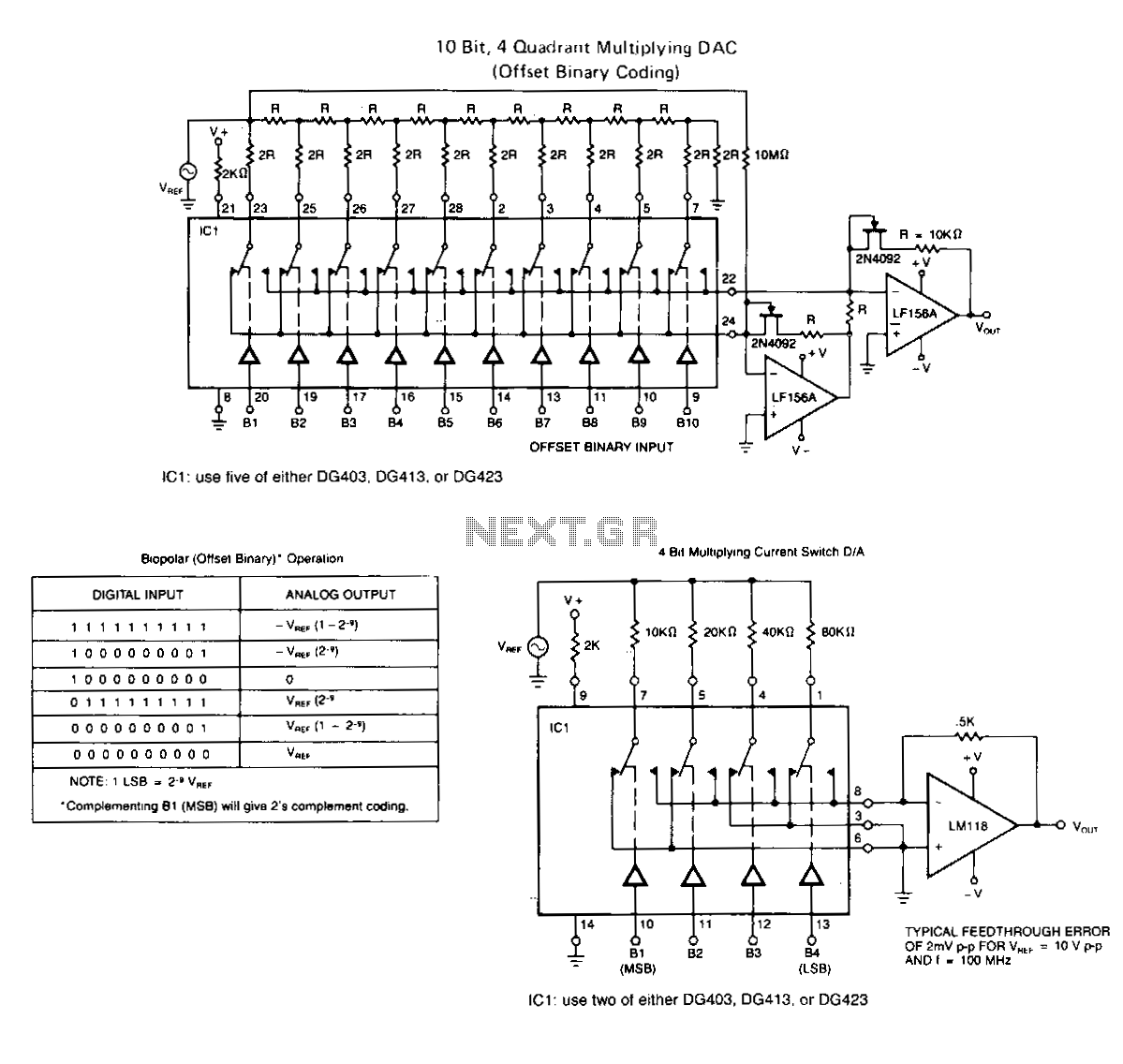
The following application circuits are intended to illustrate specific points: A 2 kΩ resistor should be placed in series with V+ to limit supply current and mitigate negative ringing of the bit inputs. Temperature compensation for Rns(on) can be...

This multimeter was designed to measure output voltage and current in a PSU, where the current sense shunt resistor is connected in series with load at the negative voltage rail. It needs only one supply voltage that can be...
This simple cable tester can be used to check two-wire cables such as coaxial cables, telephone cables, audio cables, and others. The circuit is powered by a 9V battery. To operate, plug in the cable and press the "TEST"...

The microprocessor-controlled oscillator has a frequency range of 8159 to 1, covering from 2 Hz to 20 kHz. An exponential, current output integrated circuit digital-to-analog converter (DAC) functions as a programmable current source, alternately charging and discharging a capacitor...
Warning: include(partials/cookie-banner.php): Failed to open stream: Permission denied in /var/www/html/nextgr/view-circuit.php on line 713
Warning: include(): Failed opening 'partials/cookie-banner.php' for inclusion (include_path='.:/usr/share/php') in /var/www/html/nextgr/view-circuit.php on line 713