
DIY GPS Jammer

The described device functions as a GPS signal jammer, specifically targeting the L1 frequency at 1475.42 MHz. The primary objective of this circuit is to emit noise that disrupts the ability of GPS receivers to acquire satellite signals. The operational principle relies on generating a continuous wave or noise signal at the same frequency as the GPS L1 band, effectively overpowering legitimate signals from satellites.
To construct this circuit, a few essential components are required. A suitable RF oscillator is necessary to generate the jamming signal. This oscillator can be made using a crystal oscillator or a voltage-controlled oscillator (VCO) that can be tuned to the desired frequency. The output from the oscillator is then amplified using a radio frequency amplifier to ensure that the jamming signal is sufficiently strong to interfere with GPS reception.
An antenna designed for the L1 frequency range is also crucial for transmitting the jamming signal. This antenna must be capable of radiating the noise effectively over the intended area. A simple dipole antenna or a more sophisticated patch antenna can be employed, depending on the desired range and coverage.
Power supply considerations must also be addressed, as the circuit will need a stable power source to operate effectively. Battery-powered solutions may be preferred for portability, while ensuring that the power requirements of the amplifier and oscillator are met.
It is important to note that the use of such devices is illegal in many jurisdictions due to their potential to disrupt legitimate GPS services. Therefore, careful consideration of the legal implications and ethical responsibilities surrounding the use of this technology is necessary. This device may serve as an interesting project for educational purposes or as a conversation starter, but it should not be utilized for malicious intent or in violation of regulations.Hackers listen up. Everyone understands and enjoys the utilitarian benefits that GPS has brought to our lives but what if it didn’t work any more? I suppose you could build some sort of surface to space missile robot that would systematically seek and destroy all the GPS birds in orbit, but that might attract unwanted attention by the authorities.
No, your best bet would be to build a little portable device that just affected a small area. That is exactly what this does. It works by blanketing the GPS L1 frequency (1475.42 MHz) with noise rendering the receiver unable to get an acquisition code. Without one of those it can’t see any satellites. Pretty clever. Now, I have to say that I have no idea if this circuit is going to work, I’ll leave that up to you. I mean, it’s from Phrack magazine after all so that makes it pretty hardcore. Use some common sense in the operation of this device. It might be best used as a conversation starter and that’s all. 🔗 External reference
Related Circuits
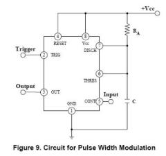
The circuit is effective for controlling the power supplied to devices such as fans, LEDs, or transformers and coils. By adjusting the pulse width, it is possible to control the speed of a fan without compromising torque. The IRF740...
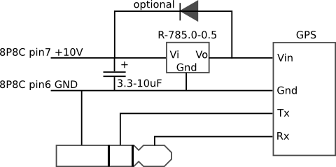
The mobile rig, a Kenwood TM-D710E, required a GPS receiver for APRS use. The GPS-710 was not readily available and was quite expensive, prompting the decision to build a custom solution. A Royaltek RGM-3600 GPS receiver was purchased on...
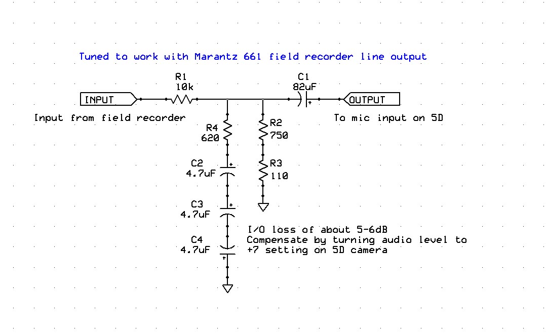
Enhancing the audio quality of the Canon 5D Mark II to achieve usable production audio involves several key steps. The initial phase of this engineering project focuses on data collection, specifically measuring the input frequency response of the 5D....

A simple low-end audio function generator is being designed to utilize a sine wave output for testing ADC resolution and as a baseband signal for RF projects, with an emphasis on achieving very low total harmonic distortion (THD). The...
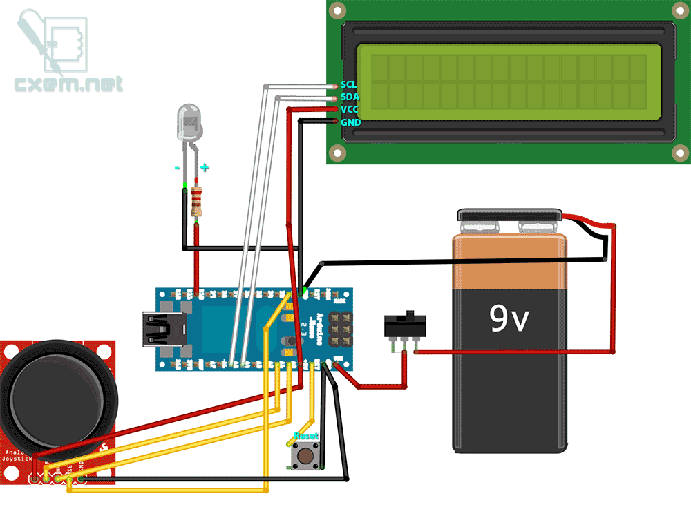
A DIY intervalometer for the Sony NEX 5N camera designed for time-lapse photography. This intervalometer is compatible with most Sony cameras, including the NEX and Alpha series. The circuit utilizes an infrared LED and a Serial LCD with four...

This circuit can jam the remote handset used to operate a TV. As long as the circuit is active near the TV, the remote handset cannot change the channels. The circuit is a simple IR transmitter operating at 38...