
diy laser power gauge
To create a cost-effective laser power measurement system, one approach involves utilizing a photodiode in conjunction with an operational amplifier (op-amp) to convert the light energy from the laser into an electrical signal. The photodiode should be selected based on its spectral sensitivity to the specific wavelength of the laser being measured.
The circuit can be designed as follows: The photodiode is placed in a reverse bias configuration to enhance its response speed. When the laser beam strikes the photodiode, it generates a current proportional to the intensity of the laser light. This current is then fed into an op-amp configured as a transimpedance amplifier, which converts the current into a voltage output. The gain of the op-amp circuit can be adjusted by selecting appropriate feedback resistor values, allowing for calibration based on the specific laser power range.
To further enhance measurement accuracy, a low-pass filter can be implemented at the output of the op-amp to reduce noise and provide a stable voltage reading. Additionally, a microcontroller can be integrated into the circuit to digitize the output voltage and provide a user-friendly interface for displaying the measured power levels. This setup allows for real-time monitoring and can be tailored to various laser types and power levels.
In summary, this circuit design provides a practical and economical solution for measuring laser power without the need for expensive commercial power meters, utilizing readily available electronic components to achieve reliable results.For some time i wanted some way to measure laser power, without spending a fortune on a power meter. First off, it is not possible to build something.. 🔗 External reference
Related Circuits
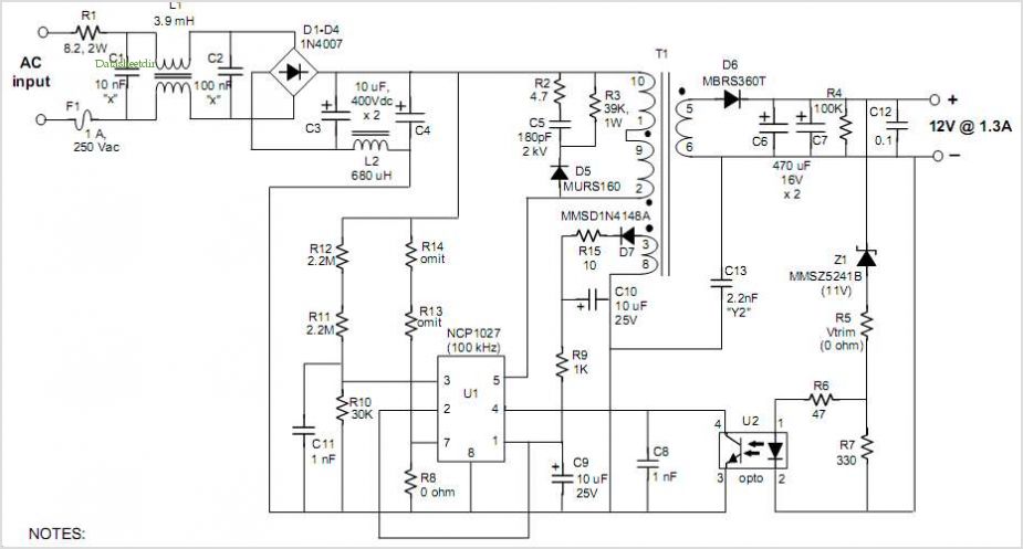
The schematic circuit design is for a 250-watt output inverter. To increase the power of the circuit, additional Q7 and Q8 transistors can be added in parallel; each pair contributes an additional 250 watts. For instance, to achieve 750...
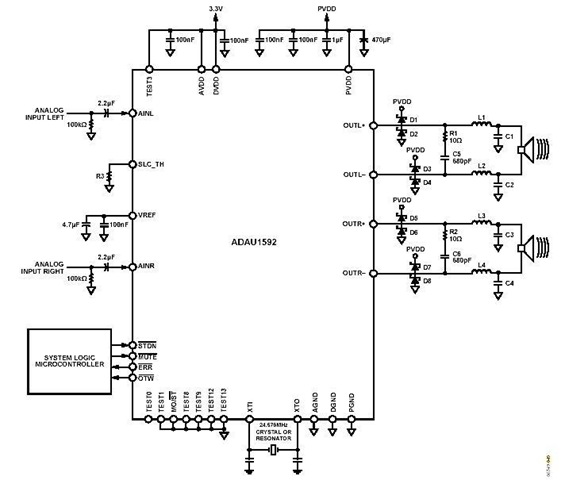
This is a stereo circuit schematic of the ADAU1592, a 2-channel, bridge-tied load (BTL) switching audio power amplifier. The ADAU1592 can be utilized in compact television sets, PC audio systems, and mini-component applications. According to the ADAU1592 datasheet, an...
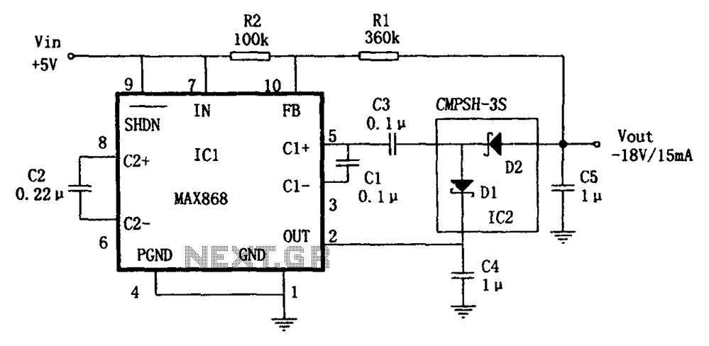
The circuit utilizes the IC1 MAX868 and CMPSH-3S to create a quadruple voltage DC/DC converter power supply. The IC1 MAX868 is an inverting charge pump regulator integrated circuit that can generate an output voltage of up to -2VIN, with...
The NCP5080 is a high-voltage boost driver specifically designed for Xenon power flashes. It features a built-in DC/DC converter that utilizes a flyback topology, allowing for the use of an external transformer to meet various high-voltage requirements. An external...
In electronic technology, the triode utilizes a variety of general components and parts. The parameters of the triode and numerous electrical parametric measurement schemes are closely related to measurement results. Therefore, in electronic design, the base pin, typological judgment,...
A schematic diagram of a micropower single-supply instrumentation amplifier circuit is presented. This circuit requires only 15µA of current and can provide over... The micropower single-supply instrumentation amplifier circuit is designed for applications where low power consumption is critical. The amplifier...