
DIY Mini Tesla Coil

The primary transformer utilizes ignition coils (induction coils) acquired from a scrap yard, offering a cost-effective method for generating high voltage to charge the capacitor. The voltage increase in an ignition coil is not determined by the turns ratio, as seen in standard transformers; instead, it is influenced by the rate of change of the current in the primary coil. Older ignition coils may not perform as effectively as newer models, as the insulating oil within the casing can degrade over time, leading to internal arcing that may damage transistors and the control circuit.
The control circuit is based on a simple oscillator utilizing an NE555 timer chip. Square wave pulses are sent to a set of four 2N3055 power transistors mounted on a large heat sink. While these transistors can switch significant power quickly, they are sensitive to voltage spikes from circuit feedback or faulty ignition coils. The ignition coil driver circuit amplifies the signal from the 555 chip, allowing effective driving of the large transistor array. Although using 2N3055 transistors is not optimal, they were the available components for this project. Modern IGBT transistors are more efficient and less susceptible to failure due to voltage spikes.
The primary coil is constructed from 2mm enameled copper wire wound around a plastic stand, with a total of six turns, and the connection is made at approximately 4.5 turns when tuned. The secondary coil is made from 0.4mm enameled copper wire wound around a plastic drainage pipe. Safety features include a short circuit switch attached to the capacitor, activated by a long plastic handle, ensuring the capacitor is fully discharged and cannot recharge during manual adjustments. An additional switch isolates power from the ignition coils, operated by an insulating pull cord.
This project incorporates several unique features compared to a conventional Tesla Coil. The topload sphere includes a small hole for gas emission, and a 5mm plastic pipe runs down the inside of the secondary coil, extending out of the plastic base.This coil operates from 12V or 24V SLA batteries. A pair of car ignition coils are used to provide around 20kV for charging the capacitor bank. The ignition coils are driven by a variable frequency square wave from a 555 timing chip and four large transistors (2N3055). Using Butane gas and air, a blue flame can be used as an interesting discharge terminal. The heated CO2 emissions provide a low pressure channel to conduct the electricity more easily than air. This produces a large plasma column above the flame. At certain spark gap discharge rates the plasma column can be made to resemble a stable double helix formation.
Small quantities of other gasses such as neon or helium can be mixed with the butane to produce slightly different colours and effects. The table below should help you find some of the components needed for this project. Capacitor Bank- The capacitor used in this project was made by combining a large number of lower valued capacitors.
By connecting smaller capacitors in series the overall voltage they will tolerate is increased. To obtain a higher storage capacity (capacitance) the capacitors can be connected in parallel. This type of capacitor bank is known as an MMC (Multi Mini Capacitors). The next version of this project will use specially designed large pulse discharge capacitors. These capacitors can be more efficient than an MMC, but they can be expensive and hard to find. Primary Transformer- Ignition coils (Induction coils) obtained from a scrap yard are used for this design. The old ignition coils provide a very cheap way of generating a high voltage for charging the capacitor.
The voltage increase in an ignition coil is not determined by the turns ratio like in normal transformers. The secondary voltage depends upon the rate of change of the current in the primary coil. Older ignition coils such as ones from a scrap yard may not work as well as new ones. Over time the insulating oil inside the casing becomes less effective and can lead to internal arcing.
This can damage the transistors and the control circuit, rendering them useless Control Circuit- The control circuit is based on a simple oscillator provided by an NE555 timer chip. The square wave pulses are sent to a set of four 2N3055 power transistors mounted on a large heat sink.
These transistors can switch a good amount of power quite quickly, but they can be sensitive to voltage spikes caused by feedback in the circuit, or faulty ignition coils. The Ignition coil driver circuit shown below shows how the signal from the 555 chip is pre-amplified, so that the large transistor array can be driven effectively.
Using 2N3055 transistors in this way is not ideal, but it is what we had available at the time for the project. Modern IGBT transistors are much more effective and less prone to failure from voltage spikes. Coils- The primary coil is simply made from 2mm enameled copper wire, wound around a plastic stand. There are six turns in total, but the connection is made at about 4. 5 turns when tuned. The secondary coil is wound from 0. 4mm enameled copper wire around a plastic drainage pipe. Safety- Attached to the capacitor is a short circuit switch that is activated by a long plastic handle.
This is used to make sure the capacitor is fully discharged, and cannot recharge whilst making any manual adjustments. There is also a switch to isolate power from the ignition coils that is activated using a insulating pull cord.
Special Features- This project has several extra features compared to a common Tesla Coil. The topload sphere has a small hole to allow gas to be emitted. A 5mm plastic pipe runs down the inside of the secondary coil, and out of the plastic base. 🔗 External reference
Related Circuits
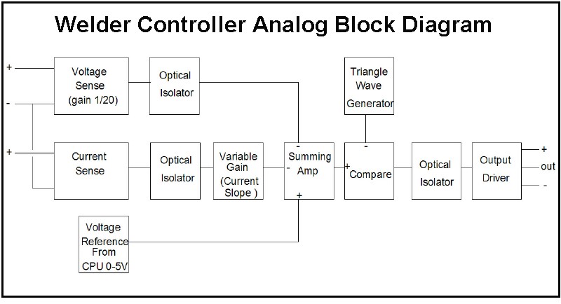
The first board is digitally controlled, while the actual welding current is analog. This design enables real-time operation without requiring the CPU to process the voltage or current. A block diagram illustrates its function: it operates as a switching...
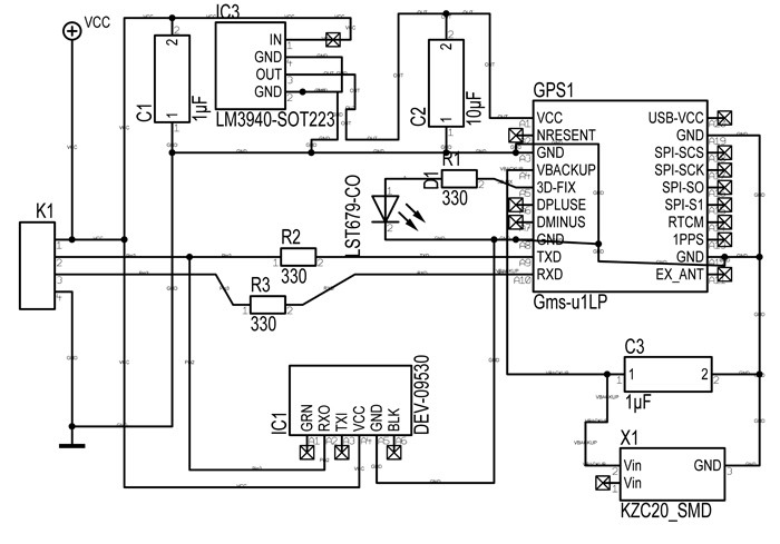
Following last year's rediscovery of radio-controlled flight, there is a growing interest in the hacking and modification potential of the budget-friendly 9-channel FlySky FS-TH9X transmitter (also marketed as Turnigy/Eurgle, etc.). The original 2.4GHz RF module and firmware are quite...
DIY Homemade Tesla Coil Tuner. Instructions for constructing a Tesla Coil Tuner using readily available components. Determine the resonant frequency of Tesla Coil components. A Tesla Coil Tuner is an essential tool for optimizing the performance of a Tesla coil...
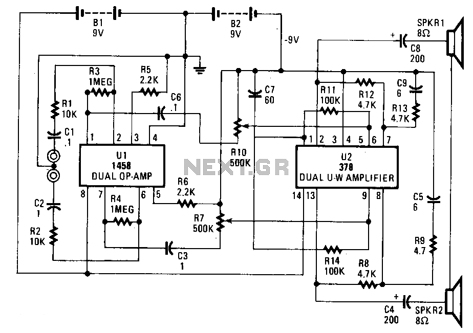
This circuit is constructed using two integrated circuits: the MC1458 dual operational amplifier, configured as a preamplifier, and the LM378 dual 4-watt amplifier. The gain of the preamplifier is determined by the resistor ratios R3/R1 for one channel and...
A DIY kinetic energy harvester utilizing the electromagnetic method to generate electricity. The materials that will be used are currently known. The project involves creating a kinetic energy harvester that converts mechanical energy from motion into electrical energy through electromagnetic...
For some time, a method to measure laser power has been sought without incurring significant expenses on a power meter. Initially, constructing such a device may seem unfeasible. To create a cost-effective laser power measurement system, one approach involves utilizing...