
DOGM128 with Arduino Hardware
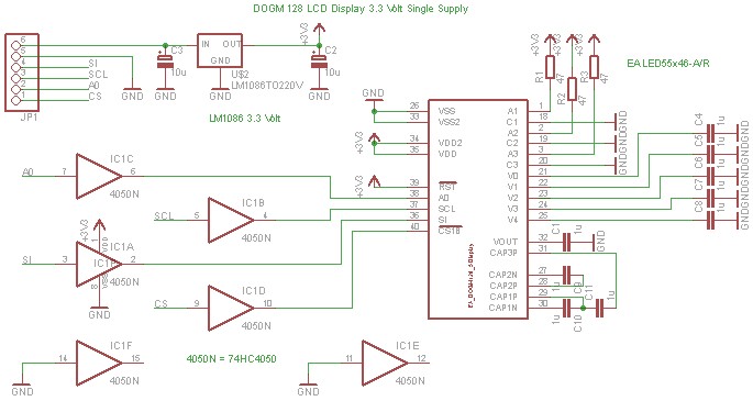
The DOGM graphics module is a versatile display component that facilitates the visualization of data and graphics in embedded systems. It operates at a supply voltage of 3.3 volts, which is essential for compatibility with various microcontroller platforms, including the Arduino. The connection configuration is crucial for ensuring proper communication between the module and the Arduino.
In the provided schematic, the DOGM graphics module is interfaced with the Arduino board. It is important to note that Pin 12 (MISO) on the Arduino should not be utilized for this connection, as it is designated for the Master In Slave Out function in SPI communication, which may interfere with the operation of the graphics module. Instead, the module requires an address line (A0) that can be connected to any available output pin on the Arduino. This flexibility allows for customization of the pin configuration based on the specific requirements of the project.
To facilitate the operation of the DOGM graphics module, the schematic also includes an HC4050 integrated circuit. This component serves as a level shifter, enabling the safe translation of voltage levels from 5 volts, which is commonly used in Arduino systems, down to 3.3 volts, suitable for the DOGM module. The HC4050 is a hex buffer/driver that can convert high logic levels (5V) to low logic levels (3.3V) without signal degradation, ensuring reliable communication between the Arduino and the graphics module.
In summary, the proper configuration and connection of the DOGM graphics module with the Arduino, alongside the implementation of the HC4050 for level shifting, are essential for achieving optimal performance and functionality in embedded applications. The schematic serves as a useful guide for engineers and hobbyists alike, enabling them to effectively integrate the DOGM graphics module into their projects.The Dogm-graphics-module should be connected to the Arduino board as shown below. Pin 12 (MISO) of the Arduino board must not be used. Additionally the Dogm-graphics-module requires an addess line (A0) which can be connected to any output port. The following schematic shows the use of the dogm-graphics-module with a 3. 3 volt supply. The level tran slation (5 volt to 3. 3 volt) is done by the HC4050 integrated circuit. 🔗 External reference
Related Circuits

The provided connections will enable configuration-free usage for most Arduino boards. Some Arduino boards, such as the Mega2560, may require custom configuration due to how the ports on the Atmel AVR microcontroller are mapped to the digital pins on...
This is a tutorial for beginners who have recently started learning about electronics. The author has prior experience in programming with C and Python. The schematic presented in this tutorial is designed for novice electronics enthusiasts who are transitioning from...
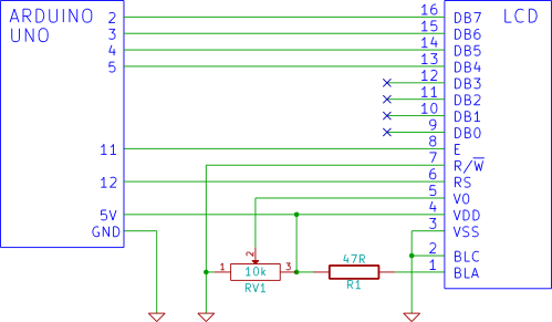
This tutorial demonstrates how to connect an LCD display to an Arduino and test it. It provides a step-by-step guide for beginners on using a breadboard to establish the connection. To connect an LCD display to an Arduino, first gather...

Agy utilized the Lilypad Arduino and LEDs for the first time in a textile project called Blinky Bike Bag, merging her skills in fabric manipulation with electronics. The bike bag is constructed from umbrella material to ensure waterproofing and...
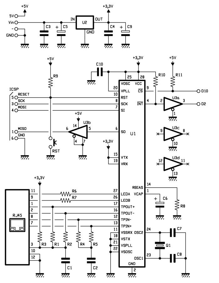
One of the most interesting shields that can be mounted on the Arduino platform is the Ethernet shield, as it enables numerous networking applications such as remote control of systems and users, web access, data publication, and more. The...
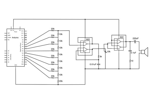
Generate sound or output analog voltages with an Arduino. This guide will demonstrate how to set up a basic digital-to-analog converter. To create a digital-to-analog converter (DAC) using an Arduino, one can utilize the Pulse Width Modulation (PWM) feature available...