
s1d13700 arduino documentation

If only the control pins (those other than D0-D7) need to be changed, the procedure closely resembles section 3a, with the pin connections specified after creating the S1D13700 object and before calling the initLCD function.
In cases where the board does not have AVR PORTD or digital pins 0 through 7 are unavailable for the LCD, two options exist. Option 1 is to modify the S1D13700.h library by changing the specified port, which is preferable for performance. Option 2 involves modifying the S1D13700.h library by uncommenting the S1D13700_CUSTOM_DATA_PINS definition and specifying individual pin settings for each data pin. This option offers greater flexibility but results in significantly reduced performance.
For example, an individual with an Arduino Mega2560 might find that port D is not fully accessible for use as a data port. They may notice that port C is available as digital pins 30 through 37 and can connect the LCD data pin D0 to Arduino pin 37, continuing this pattern until pin D7 is connected to pin 30. To inform the software library of this change, modifications to the S1D13700.h library file would be necessary.
In another case, a user of an Arduino Duemilanove may prefer to utilize the default connections but requires the RX and TX pins for communication. This user may choose to forgo the RST pin, connecting the LCD RST pin to V+ through a pull-up resistor, accepting that the display may not initialize correctly without a reset after startup.
The S1D13700 LCD controller is designed for compatibility with various Arduino boards, providing a robust interface for displaying text and graphics. The initialization process involves creating an instance of the S1D13700 class and configuring the necessary pins based on the specific board's architecture. The library facilitates the clearing of the display and the positioning of text through straightforward function calls, enabling rapid development of applications requiring visual output.
For optimal performance, the default pin configurations are recommended, especially for boards that fully support the required data pins. Custom configurations should be approached with consideration for the trade-offs between flexibility and performance. The S1D13700 library is structured to allow easy adaptation to various hardware setups, making it a versatile choice for developers working with different Arduino platforms.The provided connections will provide configuration free usage for most Arduino boards. Some Arduino boards, such as the Mega2560, will require custom configuration. This is determined by how the ports on the Atmel AVR microcontroller are mapped to the digital pins as broken out on your Arduino board. Most Arduino boards, including the Uno, Duemilanove, and Nano, have port D mapped to digital pins 0 through 7; these boards will work without any configuration changes. To determine if your Arduino will work with the default configuration, view the schematic for your board. It is available here: If your board will not support the default configuration, refer to the section of this manual covering software setup with custom pin settings.
If you`ve used the default connections, there is not configuration required. All you need to do to start displaying information is create an S1D13700 object and call the initLCD function. See the example sketch for more information. /*create our S1D13700 LCD object and name it glcd. */ S1D13700 glcd; void setup() { /*Call the setup routine */ glcd. initLCD(); /*Create a string variable */ char buf[] = "Hello World!"; /*Clear the screen */ glcd. clearText(); glcd. clearGraphic(); /*specify the column and row address where the text should be output */ glcd. textGoTo(10, 1); /*Write our string variable to the screen */ glcd. writeText(buf); } If you only need to change the configuration of the control pins (pins other than D0-D7), the procedure is very similar to section 3a.
The difference is that the pin connections must be specified after you create the S1D13700 object and before you call the initLCD function. /*create our S1D13700 LCD object and name it glcd. */ S1D13700 glcd; void setup() { /*Specify control pin connections*/ glcd. pins. rd = 10; glcd. pins. wr = 8; glcd. pins. a0 = 13; glcd. pins. cs = 11; glcd. pins. rst = 12; /*Call the setup routine */ glcd. initLCD(); /*Create a string variable */ char buf[] = "Hello World!"; /*Clear the screen */ glcd. clearText(); glcd. clearGraphic(); /*specify the column and row address where the text should be output */ glcd. textGoTo(10, 1); /*Write our string variable to the screen */ glcd. writeText(buf); } If you are using a board which does not have AVR PORTD or digital pins 0 through 7 are unavailable to the LCD you have two options.
Option 1 is to modify the S1D13700. h library by changing the port specified. Option 1 is superior from a performance standpoint. Option 2 is to modify the S1D13700. h library by un-commenting the S1D13700_CUSTOM_DATA_PINS definition, then specifying individual pin settings for each data pin. Option 2 is the most flexible option but it will result in significantly degraded performance. Example: Bob has an Arduino Mega2560. After reviewing the schematic for the Arduino Mega2560, bob determines that port D is not entirely broken out and is therefore not useable as a data port.
However, Bob notices that port C, although in reverse order, is entirely available as digital pins 30 through 37. Bob connects LCD data pin D0 to Arduino pin 37, then continues, finishing with LCD pin D7 being connected to Arduino pin 30.
In order to let the software library know about his physical change, Bob opens the S1D13700. h library file. He finds the FIXED_PORT definitions and makes the following changes. Example: Bob has an Arduino Duemilanove. Bob would love to make life easy on himself and use the default connections but he really needs the RX and TX pins for communication. Bob decides that he is willing to occasionally reset his Arduino after start up if the display does not properly initialize.
Bob then foregoes use of the RST pin and simply connects the LCD RST pin to V+ through a pull up resistor. Bob also decides he does not need to write to the screen very quickly. Bob will 🔗 External reference
Related Circuits
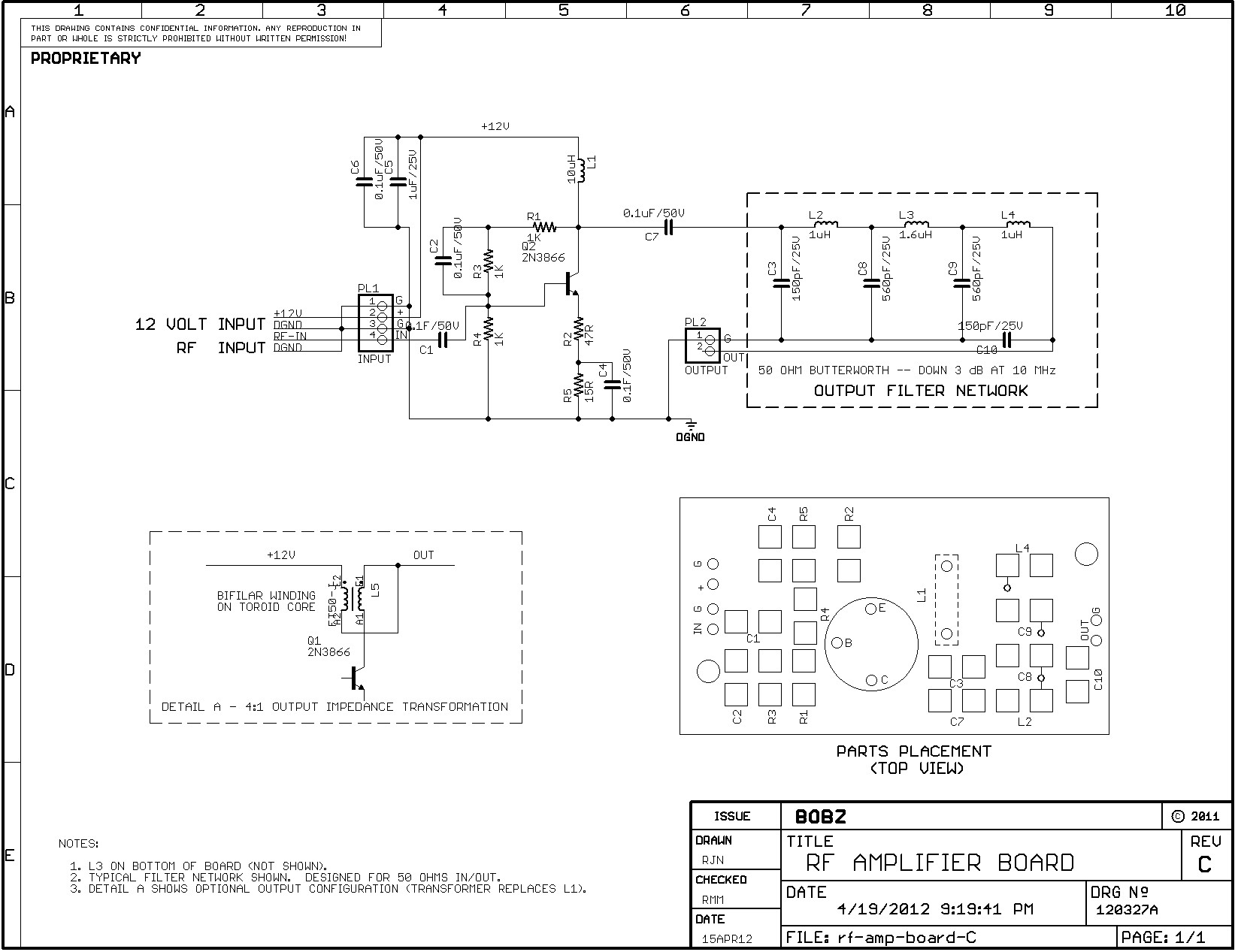
The amplifier is suitable for various projects to buffer and amplify outputs from devices such as Direct Digital Synthesizer (DDS) chips. It was initially designed to amplify the output of the 9833 DDS chip and is also intended for...
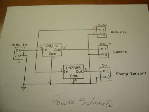
The parts list referenced is from the first page of a Make Magazine article. This list is intended for a harp that utilizes six lasers, so most quantities can be simplified to one. The schematic design based on the described...
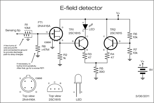
A JFET is employed to detect the electric field generated by high voltage power lines. The JFET amplifies the signal minimally but reduces the impedance and supplies current at a level appropriate for transistor amplification. The two transistors can...
This section of code outlines the main sequence of operation for the sequencer. A for loop is utilized to determine which step the sequencer is operating in. Within this loop, an address is generated using the assignByteToPins() function, which...
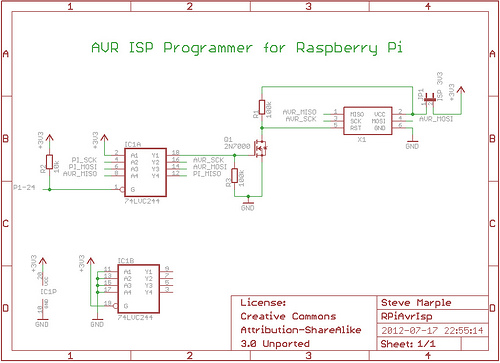
As a fully-featured Linux computer, many external programmers can be used with the Raspberry Pi to program the Atmel AVR range of microprocessors. It is also possible to utilize the general-purpose input/output lines (GPIOs) found on the Raspberry Pi...
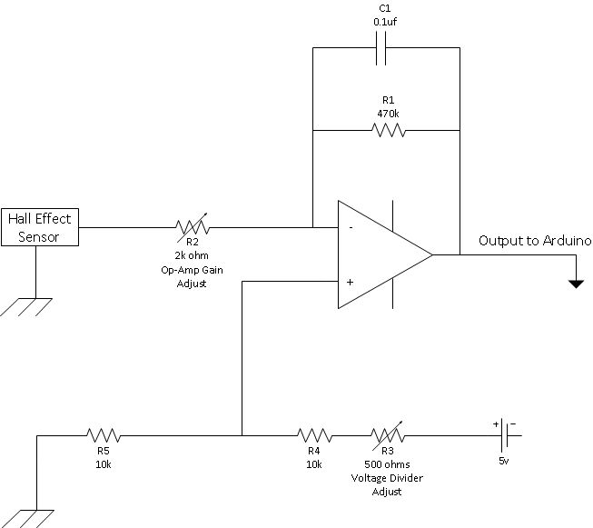
This is a straightforward schematic of an amplifier and filter. The circuit primarily features an LM124 operational amplifier configured in an inverting setup. The schematic illustrates a basic audio amplifier and filter circuit utilizing the LM124 operational amplifier. The LM124...
Warning: include(partials/cookie-banner.php): Failed to open stream: Permission denied in /var/www/html/nextgr/view-circuit.php on line 713
Warning: include(): Failed opening 'partials/cookie-banner.php' for inclusion (include_path='.:/usr/share/php') in /var/www/html/nextgr/view-circuit.php on line 713