
Door Entry Detection for MCU Based Designs
Many may wonder why photo transistors are used instead of modulated IR receivers like the TSOP1738. The TSOP series sensors were designed for data transmission, primarily from handheld remote controls to devices such as TVs or DVD players. Specific considerations were made during the design of TSOP sensors, including maximum range to ensure ease of operation in large rooms. Due to their long range, these sensors cannot assume that only directly incident rays are reaching them; rays reflected from walls can also reach the sensor. Consequently, multiple paths exist from the Tx to Rx. This characteristic, while advantageous for TV remotes, complicates door entry detection, as obstructing one path does not necessarily prevent the IR beam from reaching the receiver via an alternate path.
Two types of IR photo transistors are available: one with a transparent white casing, which is sensitive to both IR and visible light, and another with a black casing, which is only sensitive to IR radiation. This setup will not function effectively in sunlight due to the IR component present in natural light, nor will it work in rooms illuminated by incandescent bulbs (filament bulbs). Therefore, it is advisable to use this system in environments lit by fluorescent sources, such as compact fluorescent lamps (CFLs) or tube lights.
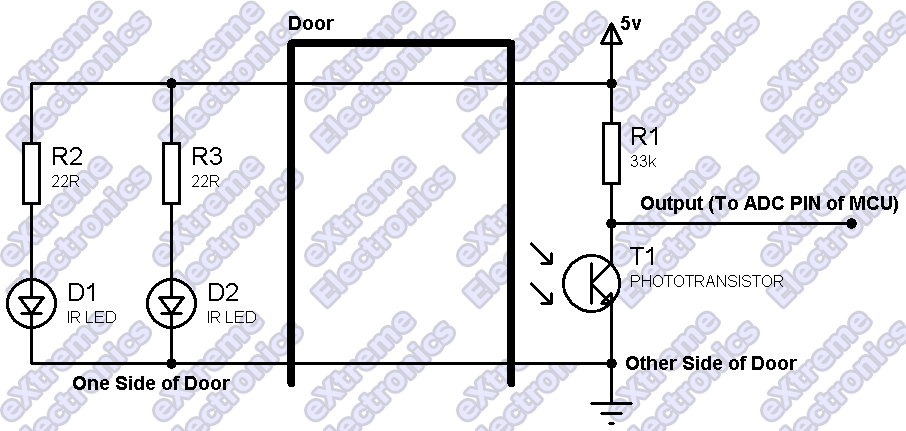
The circuit design should include the following components: an IR LED for the transmitter, a phototransistor for the receiver, and a microcontroller for processing the output signal. The IR LED should be connected to a current-limiting resistor to prevent it from drawing excessive current. The phototransistor should be connected in a voltage divider configuration to convert the light intensity into a voltage signal that can be read by the MCU. Additional filtering capacitors may be included to stabilize the voltage output from the phototransistor, ensuring reliable operation. Proper alignment of the transmitter and receiver is crucial to maintain the integrity of the IR beam, and the mounting height should be consistent to avoid misalignment due to variations in door heights. Overall, this simple yet effective circuit design provides a foundation for various applications in occupancy detection and automated control systems.This article discuss how you can detect the entry of a person in a room and get this signal inside your MCU. This is NOT a complete project but just an idea that can be implemented in many different projects. The technique is to use use an IR transmitter and a receiver pair. One side of door will have an IR Transmitter and the other side of door w ill have an IR Receiver. The transmitter (Tx in short) will continuously send IR beam to the receiver, as long as the receiver(Rx in short) will receive this beam it will give a voltage output in range of 2. 5v to 3. 0 volts. But as this beam is obstructed, for example by someone entering the room, the receivers output will tend towards 4.
5 The IR Transmitter can be made on a small PCB as shown below. It has four mounting holes to fix it in the wall near the door. Please use 1 Watt resistor for R2 and R3 (22ohms). As you can see the optimal distance between the transmitter and receiver is 2. 0ft. to 3. 5ft. While the Rx/Tx should be mounted at the height of 3. 5ft. from the ground. Many people would ask why I have used photo transistors and not modulated IR receivers like TSOP1738 etc. The reason is that the TSOP series sensors were designed for data transfer, mainly from hand held remote control to devices like TV`s or DVD players.
So following points were kept in mind while designing TSOP sensors. Maximum range (So that remote could be easily operated in big rooms), since these have long range you cannot assume that only the rays that are directly incident on the Rx are the only rays reaching it, rays bounced from walls also reach the sensor. So actually their are more than one path from the Tx to Rx. This makes door entry detection impossible because if the person entering the room cuts one path, the ray would reach from the alternate path!
As you can see this situation is actually good for a TV remote (for which TSOPs were designed) but not for our application. Their are two types of IR Photo transistor available. One is transparent white, this one is sensitive to both IR and Visible radiations. The second one is with Black case, this one is only sensitive to IR radiation. The setup will not work in presence of sunlight due to presence of IR component in it. Nor will it work if the room is lit with incandescent bulbs (filament bulbs), so it is recommended to use this in room that is lit with florescent source like CFLs or Tube lights.
🔗 External reference
Related Circuits
This simple door chime protects the door and emits a loud alarm tone in the event of a theft attempt. The circuit is straightforward and battery-operated. A Normally Closed (NC) reed switch and magnet are utilized to trigger the...
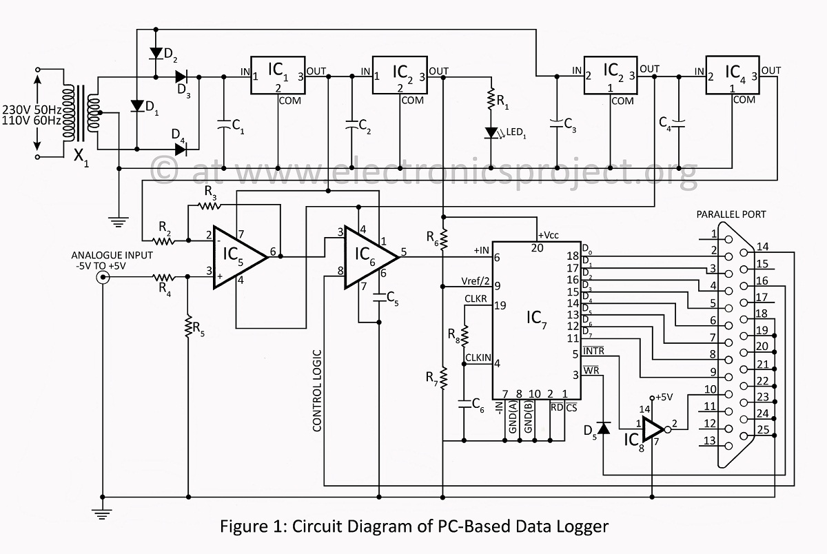
A PC-based data logger utilized in physics laboratories for automating simple experiments and monitoring slowly varying physical variables across various PC-based projects. The PC-based data logger serves as an essential tool in physics laboratories, enabling the automation of experiments and...
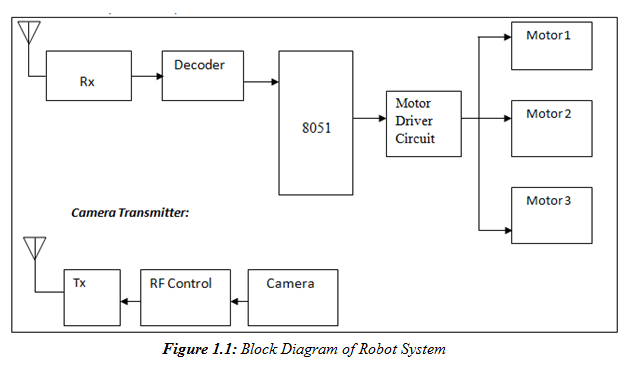
A prototype model of an agriculture-based robot has been developed to address the challenges faced by farmers who have traditionally relied on manual labor for cultivating their lands. The increasing urbanization has led to a shortage of labor, as...
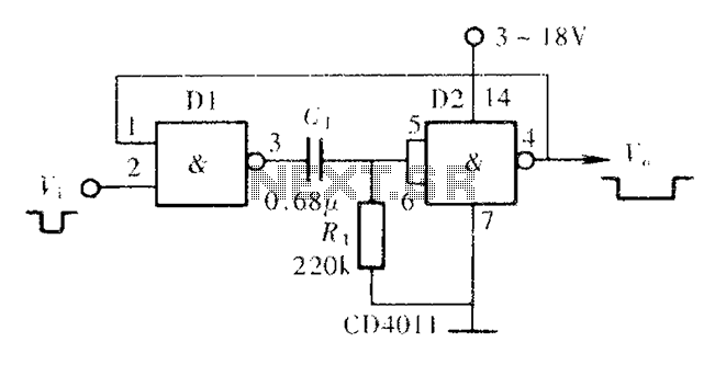
A CMOS NAND gate or NOR gate can form a monostable multivibrator, commonly referred to as a single-shot. This circuit is extensively used to delay pulse signals, allowing for signal stretching and shaping. The main principle involves utilizing the...
Additional photos of the cutter components have been located. These images depict the conical inserts attached to the quick-change nozzle, which serve to minimize contamination of the cutting stream. The cutter assembly features a quick-change nozzle designed for efficient replacement...
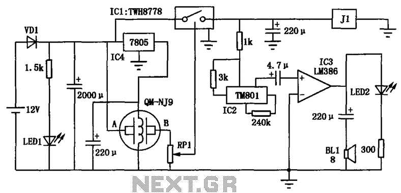
The alcohol detection alarm controller circuit is illustrated in the figure. It utilizes the QM-NJ9 alcohol gas sensor, which detects the presence of alcohol vapors. When alcohol is detected, the resistance between the AB-QM-NJ9 decreases, causing the wiper of...
Warning: include(partials/cookie-banner.php): Failed to open stream: Permission denied in /var/www/html/nextgr/view-circuit.php on line 713
Warning: include(): Failed opening 'partials/cookie-banner.php' for inclusion (include_path='.:/usr/share/php') in /var/www/html/nextgr/view-circuit.php on line 713