
simple tiny door guard

The door chime circuit operates by integrating several key components that work together to provide a reliable security solution. The Normally Closed (NC) reed switch is a crucial element, as it ensures that the circuit remains inactive when the door is closed. The reed switch responds to the magnetic field generated by the magnet affixed to the door, maintaining an open circuit under normal conditions.
When the door opens, the magnet moves away from the reed switch, causing the contacts to close and complete the circuit. This action energizes the UM3561 integrated circuit, which begins generating alarm tones. The tone selection feature, enabled by pin 6, allows the user to choose the desired sound based on the application's specific needs. The resistor connected to pins 7 and 8 sets the oscillation frequency, which can be fine-tuned to achieve the desired sound characteristics.
The Zener diode plays a vital role in voltage regulation, ensuring that the UM3561 operates within its specified voltage range, thus preventing damage and ensuring reliable performance. The NPN transistor amplifies the output signal from the UM3561, allowing the circuit to drive a loud siren. This amplification is essential for ensuring that the alarm can be heard clearly, deterring potential intruders.
Installation of the circuit requires careful placement of components. The circuit board should be securely mounted within the door frame, while the reed switch must be positioned close enough to the door to ensure reliable operation. The use of double-sided adhesive tape for the magnet allows for easy installation and adjustment, ensuring optimal performance of the door chime system. Overall, this simple yet effective door chime circuit provides an accessible solution for enhancing security in residential or commercial settings.This simple Door Chime protects the door and gives a loud Alarm tone when there is an attempt of theft. The circuit is too simple and battery operated. A Normally Closed (NC) reed switch and magnet is used to trigger the circuit. Alarm generator is the popular ROM IC UM 3561. This 8 pin IC has an inbuilt oscillator to generate 4 siren tones like, Ambulance siren, Police siren, Fire brigade siren and Gun sound. The different tones can be selected using its pin 6 connected to VCC, Ground or not connected. Frequency of oscillation is determined by the 220K resistor connected to the pins 7 and 8 of the IC. UM 3561 is the low power IC and its maximum voltage rating is 3 volts. So Zener diode ZD is used to give 3 volts supply to IC. Medium power NPN transistor T1 amplifies the output pulses from IC1 to a loud siren. Magnet can be a small sized one that is to be fixed in the door using double sided adhesive tape. Fix the circuit board in the door frame. Fix Reed switch in the door frame, very close to the door. So that, when the door is closed, the magnet will pull the contacts of the reed switch to break supply to the IC. When the door opens, contacts of the reed switch make contact and IC gets power to give alarm. 🔗 External reference
Related Circuits

In certain situations, it is beneficial to enhance the range of available control, and this circuit serves that purpose by receiving the infrared (IR) signal from a remote control and re-transmitting it, potentially around corners or into other rooms....

Basically, this is a frequency-current converter. It is used as a frequency meter. Calibrating it can be used as a tachometer. Please be aware this is an experimental project; it wasn't connected to any vehicle, but it should work...
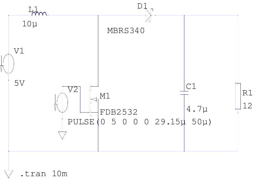
The supply voltage is 5V, and the goal is to increase it to 12V with a load current of 1A, resulting in an output power of 12W. A switching frequency of 20kHz has been selected, requiring a duty cycle...

A simple lab power supply electronic project can be designed using this circuit diagram, which is based on the LM2576 monolithic integrated regulator that provides all the active functions for a step-down (buck) switching regulator. As seen in the...

This is a DC regulator circuit that can provide multiple output voltages simply. It functions as a simple step-down DC converter and is designed with a fixed resistor R1. The described circuit operates as a DC voltage regulator, specifically designed...

This simple metal detector requires only a handful of components and an evening's work. Built around a cmos4011 IC, is very robust and versatile. The 250 kHz reference oscillator is built with two gates (U1/1 and U1/2), C1, R1...
Warning: include(partials/cookie-banner.php): Failed to open stream: Permission denied in /var/www/html/nextgr/view-circuit.php on line 713
Warning: include(): Failed opening 'partials/cookie-banner.php' for inclusion (include_path='.:/usr/share/php') in /var/www/html/nextgr/view-circuit.php on line 713