
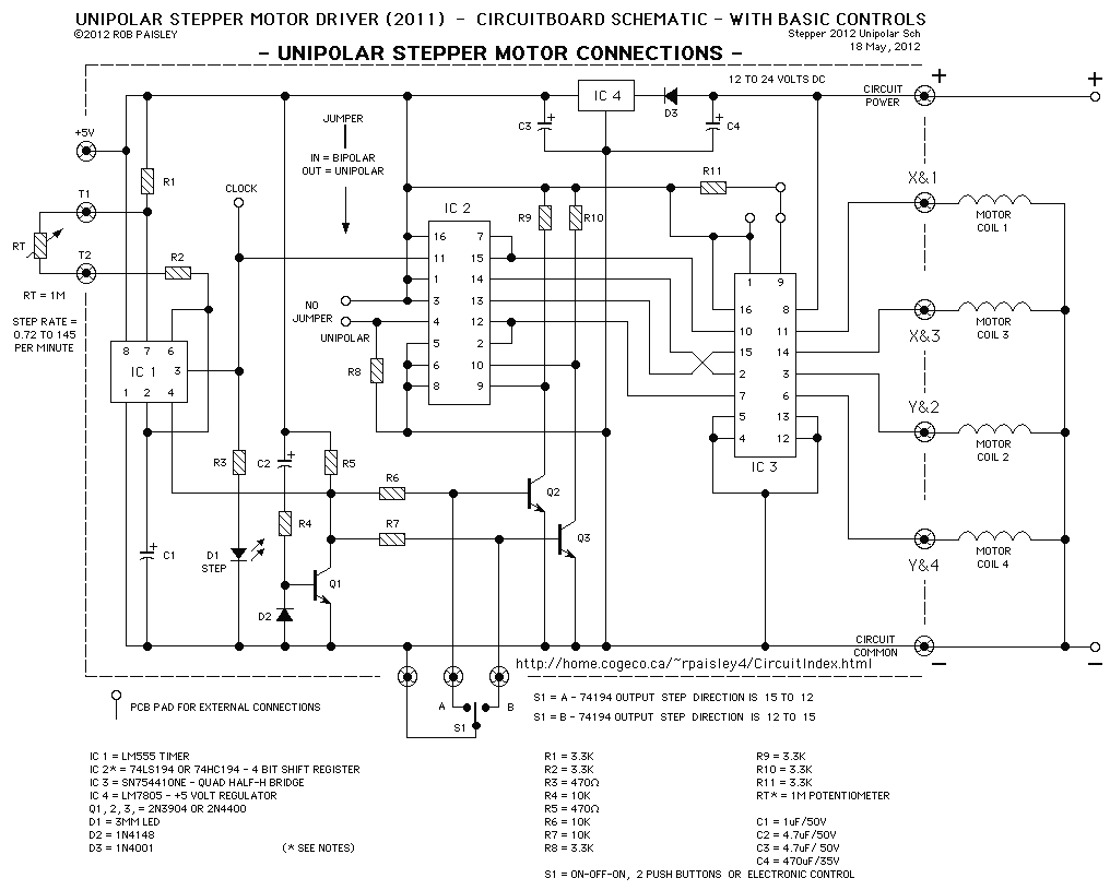
Driving bipolar stepper with uC
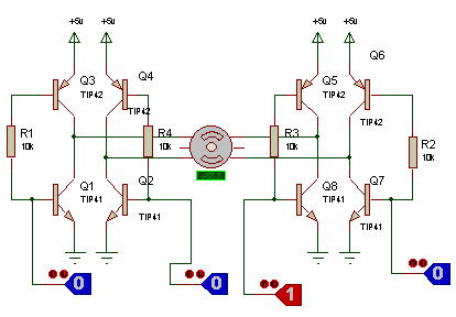
The use of a bipolar motor requires a different driving technique compared to a unipolar motor. Bipolar motors typically have two coils that need to be energized in a specific sequence to create a rotating magnetic field. This is achieved by reversing the current direction in the coils, which is not applicable to unipolar motors that use a single direction of current flow through the coils.
To adapt the existing schematic designed for a unipolar motor to work with a bipolar motor, the following modifications should be considered:
1. **Coil Configuration**: Ensure that the schematic includes two coils (A1 and A2) that can be driven independently. Each coil should be connected to an H-bridge configuration or a similar driver circuit that allows for current direction reversal.
2. **Microcontroller Outputs**: The PIC 12F508 will need to control the H-bridge transistors or MOSFETs. This can be achieved by using four output pins from the microcontroller, where each pin controls one side of the H-bridge, allowing for the necessary current direction changes to energize the coils in the correct sequence.
3. **Control Logic**: Implement a control algorithm that sequences the activation of the coils. This can be done using either a timer interrupt or a main loop that checks the desired step position and activates the coils accordingly.
4. **Power Supply**: Ensure that the power supply voltage and current ratings are suitable for the bipolar motor specifications. The driver circuit must handle the increased power requirements compared to a unipolar setup.
5. **Feedback Mechanism**: If precise control is necessary, consider integrating a feedback mechanism using encoders or Hall effect sensors to monitor the rotor position and adjust the drive signals accordingly.
By making these adjustments, the schematic can be effectively modified to drive a bipolar motor using the existing microcontroller setup.I have a bipolar motor, and software written for PIC 12F508 to drive unipolar motor. Is the schematic in attachment correct for this purpose? Coil A1, .. 🔗 External reference
Related Circuits
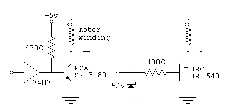
To control a stepper motor, each winding must be energized individually in a specific and timed sequence. This energization is carried out by a driver circuit, which acts as an amplifier. The timing is managed by an indexer circuit,...
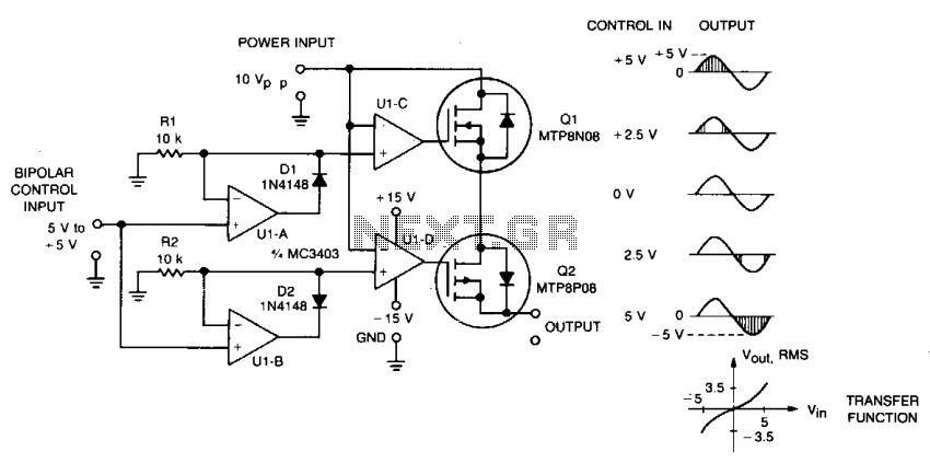
This circuit accepts bipolar control inputs of ± 5 V and provides a phase-chopped output to a DC load (such as a servo motor) of the same polarity as the input. The RMS voltage of the output is closely...
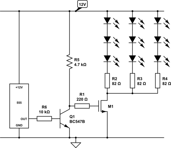
Create a circuit using a 555 timer to operate 72 LEDs simultaneously. A circuit has already been constructed, but there are concerns regarding its safety and longevity. A picture of the circuit is provided for review, and assistance is...
The following diagram is for the main circuit of the motor driver. A testing version is shown near the end of this page. It is laid out differently and shows the SN7474 in logic block form and LEDs are...
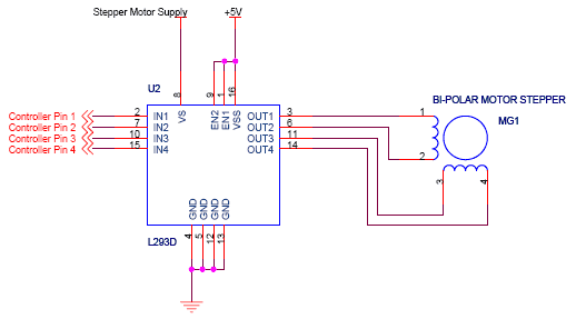
The circuit features four pins labeled "Controller pin 1," "Controller pin 2," "Controller pin 3," and "Controller pin 4," which are responsible for controlling the motion and direction of the stepper motor based on the step sequence programmed into...
It is widely recognized that power-saving regulations necessitate very low power consumption during standby conditions for all equipment continuously connected to mains power. In the standard version of the power supply, standby power consumption is approximately 9.0 W for...