
Driving Stepper
The M1 stepper motor, sourced from an obsolete disk drive, features a configuration of five pins: one common pin and four coil pins. The measured resistance between the common pin and each coil pin is approximately 75 Ohms, indicating a relatively low impedance, which is typical for stepper motors. To operate each coil effectively, a driving current of about 60mA is required when powered by a +5V supply.
To facilitate the increased driving capacity necessary for controlling the stepper motor, a Darlington transistor array, specifically the ULN2003, is employed. This component is designed to handle higher current loads, with each output capable of supplying a maximum of 500mA at voltages up to 50V. The arrangement of the circuit involves connecting four output pins from the control chip (noted as P1.4 to P1.7) to the inputs of the ULN2003. This configuration allows for efficient control of the motor coils.
Additionally, four 4.7kΩ resistors are incorporated into the design to enhance the current sourcing capabilities from the +5V supply, thereby ensuring that the 2051 chip can drive the ULN2003 effectively. This resistor setup serves to limit the current flowing into the inputs of the ULN2003, protecting the control logic while still providing sufficient drive for the transistor array.
An optional serial port interface is mentioned for further exercises, allowing for additional control and communication with the stepper motor system. The integration of the stepper motor in various applications has been widely documented, providing a wealth of technical insights and practical implementations for users interested in harnessing stepper motor technology.M1 is a stepper taken from an old disk drive. There are five pins, i.e., common, coil 1, 2, 3 and 4. Resistance measured between common pin and each coil is about 75 Ohms. Driving current for each coil is then needed about 60mA at +5V supply. A darlington transistor array, ULN2003 is used to increase driving capacity of the 2051 chip. Each output provides 500mA max at 50V. P1.4 to P1.7, four output pins are connected to the input of the ULN2003 as shown in the circuit. Four 4.7k resistors help the 2051 to provide more sourcing current from the +5V supply. The serial port is optional for your exercises. Many have provided useful technical, and application of using stepper, see the links below. 🔗 External reference
Related Circuits
The circuit features almost open collector outputs with a withstand voltage of 60V and a continuous conduction current of 0.3A. The typical voltage drop is 0.4V, with a peak current capability of 9A. It can directly drive two windings...
A basic circuit of the 89C2051 can be constructed using point-to-point soldering on a universal printed circuit board (PCB). An ordinary 20-pin socket should be utilized, avoiding the use of a circular-pin socket. D1 represents a small dot LED....
The SM5021 series consists of crystal oscillator module ICs fabricated using NPC's Molybdenum-gate CMOS technology. These ICs integrate high-frequency, low current consumption oscillator and output buffer circuits. They feature highly accurate thin-film feedback resistors and high-frequency capacitors, which eliminate...
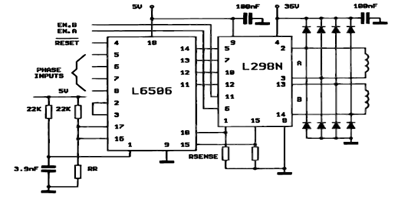
The following figure illustrates the control circuit for a two-phase bipolar stepper motor utilizing the current controller L6506. The L6506 integrated circuit generates the necessary signals to drive the inputs of the L298 bipolar stepper motor circuit driver. The circuit...
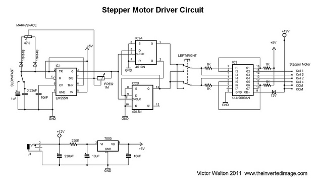
The commonly used 555 timer is configured for a variable mark/space ratio, which is essential for this application. Additionally, two D-type flip-flops (4013) are employed to provide the necessary count for the ULN2003 stepper motor driver. ULN2003 components may...
A bipolar motor is being utilized, along with software developed for the PIC 12F508 microcontroller, which is intended for driving a unipolar motor. The correctness of the attached schematic for this application is in question. The use of a...