
Single-phase double-winding motor driving
The circuit operates as a versatile and efficient driver for single-phase brushless DC motors, leveraging an internal Hall effect sensor to monitor the magnetic field. The outputs are designed to provide complementary signals that facilitate the control of motor windings, ensuring smooth operation and efficient energy use. The internal temperature compensation feature is particularly advantageous, allowing the circuit to maintain performance across a wide temperature range, making it suitable for various environmental conditions.
The design minimizes external component requirements, which contributes to a lower overall cost and a more compact system layout. The inclusion of a freewheeling circuit helps to mitigate voltage spikes that can occur during motor operation, protecting the output transistor from potential damage. This aspect is crucial in ensuring the longevity and reliability of the circuit in practical applications.
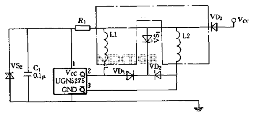
When implementing this circuit, careful consideration must be given to the maximum starting current, as exceeding the IC's specified limits can lead to malfunction or damage. The relationship between the motor's power supply voltage and winding resistance plays a significant role in determining this starting current, and thus should be calculated accurately to ensure safe operation. Overall, this circuit provides a robust solution for driving brushless DC motors with a focus on reliability, efficiency, and cost-effectiveness.Almost open collector two outputs, open a withstand voltage of 60V, continuous conduction current of 0.3A, voltage drop typical type is 0. 4V, Zhang peak current of 9A. Can dir ectly drive two windings and easily compose minimal external components, low cost, monolithic single-phase brushless DC motor output Q (2 feet) and acupuncture (3 feet) are complementary. Hall generator when the internal sense the magnetic flux density exceeds the action value by BOP, Q goes low, and after about acupuncture ws when delayed transition to high.
Conversely, anti-polarity magnetic induction Back BRP value, Q goes high, and acupuncture is low. Since the circuit with internal temperature compensation circuit, in -20 ~ + 80C within the operating temperature range, can maintain a stable switch point. This circuit supply voltage as 5-14V.T ten z5c when, Bc) p . 0025 ~ 0.025T.BRP eleven .025-0.0025T, BHYs O.OIT. Application Circuit Example in, VD, VD, and S. freewheeling circuit composed of two windings and clamping of spikes induced electromotive force to protect lc output transistor.
when you use this circuit to be noted that, when the motor is started, the maximum starting current (determined by the motor power supply voltage and winding resistance) should not exceed the ICs current most large allowable value.
Related Circuits
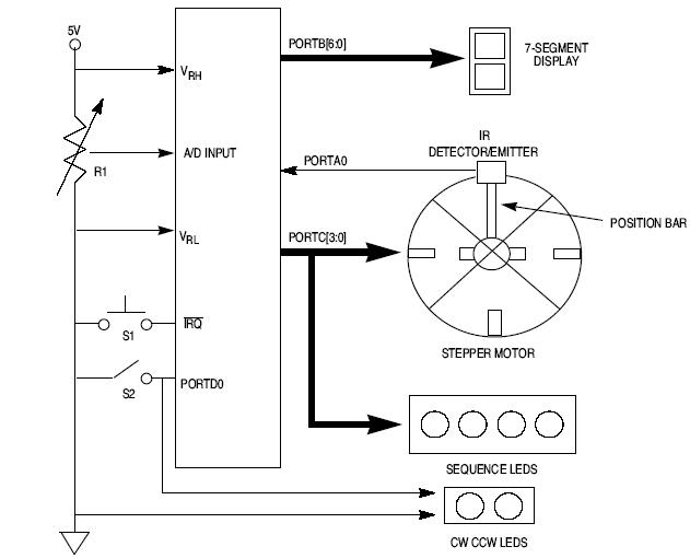
This article explains how to design a stepper motor system using an 8-bit Freescale microcontroller - MC68HC11E9. The design of a stepper motor system utilizing the 8-bit Freescale microcontroller MC68HC11E9 involves several key components and considerations to ensure effective control...
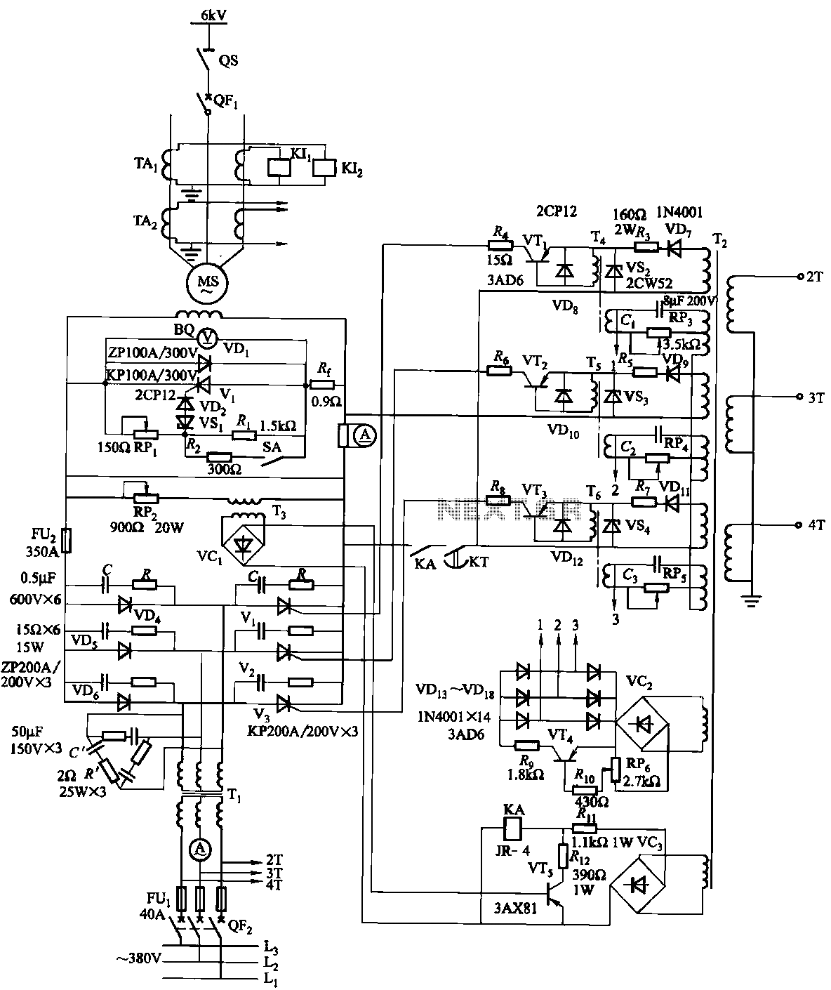
The excitation device for a light-duty synchronous motor rated at 625 kW has been initiated. The triggering circuit of the device consists of three identical RC phase-shift flip-flops. Adjustment potentiometers RP3 to RPs are used to set the RC...
A circuit that will find enough applications. Basically, the designing became in order to exist delay in quench one or more lamps in a stairwell or in any other space exists this need. It can become use for the...
This is a Class D audio amplifier circuit that is used to control PWM motor speed. This circuit has two advantages for battery-powered portable devices. First, The Class D audio amplifier circuit is designed to efficiently manage the speed...
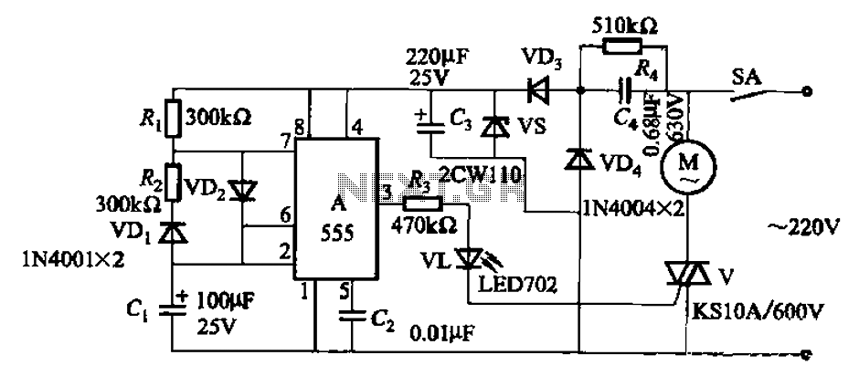
The circuit depicted in Figure 3-16 utilizes a 555 IC (Integrated Circuit) as the control element. It features a capacitive step-down circuit and incorporates a bidirectional thyristor (V) for intermittent motor control operation. By adjusting the resistance values of...
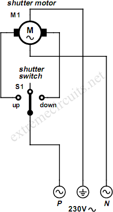
An electrically operated rolling shutter typically features a standard control panel equipped with a three-position switch that allows for up, down, and stop functions. The electrically operated rolling shutter system is designed to provide convenient control over the opening...
Warning: include(partials/cookie-banner.php): Failed to open stream: Permission denied in /var/www/html/nextgr/view-circuit.php on line 713
Warning: include(): Failed opening 'partials/cookie-banner.php' for inclusion (include_path='.:/usr/share/php') in /var/www/html/nextgr/view-circuit.php on line 713