
Multi-way pocket alarm circuit
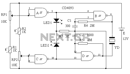
This two-way alarm circuit leverages the characteristics of a Schmitt trigger to provide reliable temperature monitoring with both upper and lower limits. The use of thermistors allows for precise temperature sensing, while the piezoelectric buzzer and LEDs serve as effective alert mechanisms. The design's low power consumption is particularly advantageous for battery-operated applications, ensuring prolonged operation without frequent battery replacements. The versatility of the circuit also allows for modifications, such as integrating different sensing elements, to accommodate various environmental monitoring needs. The schematic design should clearly indicate the connections between the components, including the power supply, input sensors, and output indicators, ensuring ease of assembly and troubleshooting.This is a two-way can set the alarm circuit which uses a Schmitt IC, with responsive and sound and light show, small size, low power consumption, all of the elements is only 13, a very low cost. This circuit is divided into two parts by the A, B and R4, C1 composition limit alarm. And in C, D and R5, C2 constitute the lower limit alarm function, the circuit shown in Figure 1.Usually RP1, RP2 are provided two upper and lower alarm point, the A and C inputs are high, the outputs are low leaving the oscillator are halted. When the temperature is too high, the thermistor resistance R1 decreases, the output high A, B start-up, the piezoelectric ceramic YD a high-pitched beep.
At the same time, the light emitting diode LED1 lights on to indicate overheating. When the temperature is too low, the thermistor R2 resistance increases output high of C, D start-up, the piezoelectric sheet issued YD bass tone beep. Light emitting diode LED2 display temperature is too low.Since CMOS circuit static power consumption is extremely small, only microampere current level, so static power consumption mainly in the RP1, RP2 and thermistors.
If we can use resistance at more than a hundred k special temperature resistance, RP1, RP2 a corresponding increase in the scale drawing press, the static power consumption can be controlled very small, it is extremely beneficial to prolong battery life.Component list as follows: Number Name Type Quantity R1,2 thermistor 1K 2 R3 resistance 3K 1 R4,5 resistance 2M 2 RP1,2 adjustable resistor 10K linear 2 Polyester capacitors C1 300P 1 Polyester capacitors C2 1000P 1 LED1,2 emitting diode µ3mm 1 Schmidt integrated circuit or IC CD4093 MC14093 1 YD piezoelectric buzzer µ20mm HTD20A-1 type 1 E battery lighter dedicated 12V small battery 1 The alarm uses the components is not large, do like so small matchbox.If instead of using photosensitive resistance thermistor can be used as the light intensity alarm. It can also be the other input of the Schmitt trigger use down as light, temperature bifunctional two-way alarm.
It leads to a control signal from the LED fill light, humidification (ultrasonic humidifier) to compose automatically fill light and humidity controller.
Related Circuits
The automotive electronic locks circuit principle is illustrated with the dedicated lock IC 5G058. It features an external key switch connected to the positive power supply. The circuit includes six valid input keys, unlock keys S1 to S6, which...
The electronic circuit simulates bird sounds under varying lighting conditions, particularly influenced by neon light irradiation, resulting in fluctuating and changing tones. The sound produced is continuously variable. The schematic of this circuit is provided. The described electronic circuit utilizes...
This alarm siren circuit produces a warbling sound, suitable for use in toys or security alarms. The circuit employs two 555 IC oscillators. The first oscillator generates the audio frequency, while the second oscillator creates a modulating signal. This...
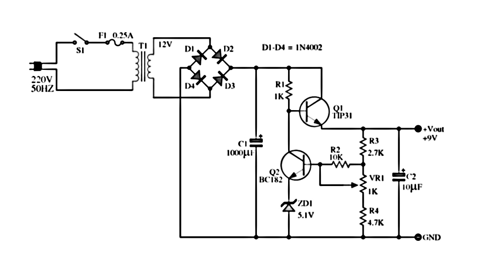
The power supply described utilizes a regulator composed of two NPN transistors. One transistor functions as the power regulator, while the other controls the output voltage. This power supply offers an adjustable output voltage range of 6-12 VDC. The...
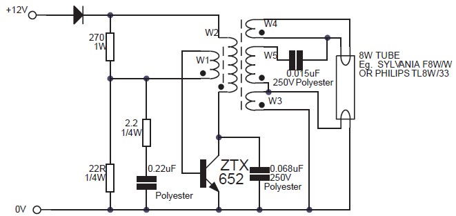
This circuit is an 8W inverter designed to drive an 8W fluorescent lamp from a 12V power supply, utilizing an inexpensive inverter based on a ZTX652 transistor. The inverter operates from power supplies ranging from 10V to 16.5V, achieving...
A magnetic switch is a circuit designed to respond to surrounding magnetic fields detected by the sensor. This series of magnetic switches employs limit switch sensors that include an additional metal plate capable of responding to a magnet. The...
Warning: include(partials/cookie-banner.php): Failed to open stream: Permission denied in /var/www/html/nextgr/view-circuit.php on line 713
Warning: include(): Failed opening 'partials/cookie-banner.php' for inclusion (include_path='.:/usr/share/php') in /var/www/html/nextgr/view-circuit.php on line 713