
DS1307 based Clock using lcd
The DS1307 is a low-power, I2C real-time clock that maintains accurate time and date information. It operates on a supply voltage of 1.8V to 5.5V and can function in a wide range of temperatures, making it suitable for various applications. The chip includes a 56-byte SRAM for data storage, which can be used for storing user-defined data.
The real-time clock is capable of tracking seconds, minutes, hours, day, date, month, and year, with leap year compensation. The DS1307 communicates with microcontrollers via the I2C protocol, allowing for easy integration into various electronic projects.
To implement this project, the DS1307 must be connected to a microcontroller, such as an Arduino or Raspberry Pi, using two wires for the I2C communication (SDA and SCL). Additionally, a 32.768 kHz crystal oscillator is required to ensure accurate timekeeping. A backup battery, typically a CR2032 coin cell, is also necessary to maintain timekeeping during power outages.
The circuit design includes pull-up resistors on the SDA and SCL lines to ensure proper logic levels during I2C communication. The microcontroller can be programmed to read the time data from the DS1307 registers and display it on an LCD or send it to a connected device.
In summary, the DS1307 real-time clock project offers a reliable solution for timekeeping in electronic applications, utilizing its built-in oscillator and I2C communication capabilities for seamless integration.This project gives you a real time clock with the RTC chip DS1307. This RTC chip has inbuilt oscillator for clock and it has its own registers for full. 🔗 External reference
Related Circuits
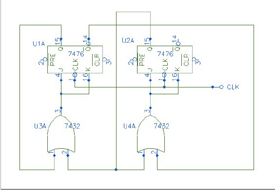
Q1 and Q2 form a table. On the left side, list the four possible states of Q1 and Q2; on the right side, write the values that Q1 and Q2 will assume after the next clock pulse. The table...
The following circuit illustrates a Boost Converter Circuit Diagram. This circuit is based on the 555 IC. Features: it only requires off-the-shelf components. The Boost Converter is a type of DC-DC converter that steps up the input voltage to a...
This article is intended for complete beginners with servo motors. It provides an overview of the basic theory behind servo motors and offers detailed instructions on how to utilize them with AVR microcontrollers such as the ATmega32. Servo motors are...
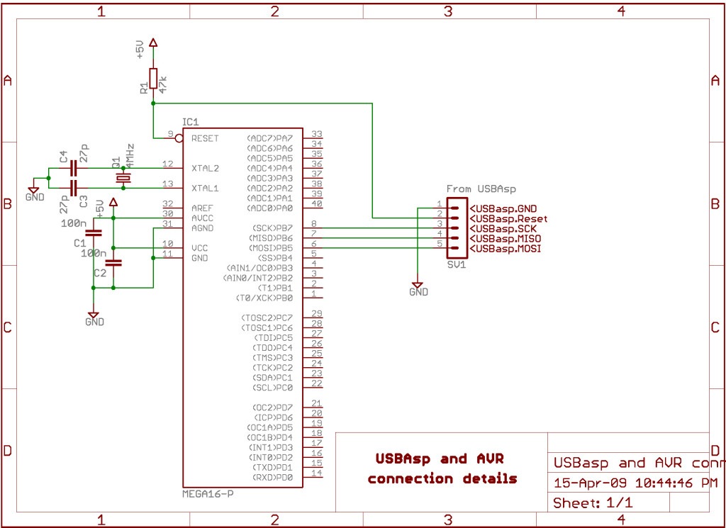
AVRDude is a program designed for burning hex code into microcontrollers. USBasp is a USB-based programmer for AVR microcontrollers. This tutorial will demonstrate how to use AVRdude to burn hex files into an AVR microcontroller using USBasp. The AVRdude...
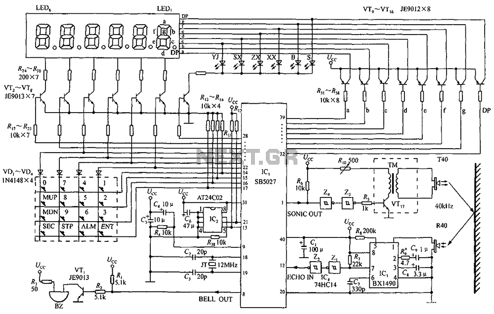
A circuit diagram of an ultrasonic range finder is constructed using a clock with a calendar and the Ultrasonic Ranging IC SB5027. The ultrasonic range finder circuit utilizes the Ultrasonic Ranging IC SB5027, which is designed to measure distances by...
The following circuit illustrates a Bluetooth-based smart home circuit diagram. This circuit is based on the ULN2003 integrated circuit (IC). Features include an LCD and LED. The Bluetooth-based smart home circuit utilizes the ULN2003 IC, which is a high-voltage, high-current...