
DTMF decoder using MT8870DE
The described telephone system represents a significant advancement in telecommunication technology, transitioning from manual operator intervention to automated electronic systems. The core of this system relies on dual-tone multi-frequency (DTMF) signaling, which is essential for the operation of modern telephony. Each key on the keypad corresponds to a specific frequency pair, allowing for distinct identification of the pressed key. The implementation of a dial tone generator and decoder circuit is critical, as it facilitates the conversion of analog signals into digital data that can be processed by a computer.
The circuit design for the decoder typically includes an analog-to-digital converter (ADC) to capture the incoming DTMF tones. The ADC samples the analog signals at a sufficient rate to accurately reproduce the frequency components. After sampling, the signals are processed through a digital signal processor (DSP) or a microcontroller equipped with DTMF decoding algorithms. These algorithms analyze the frequency components of the incoming signal, identifying the specific tone pairs and translating them into binary outputs corresponding to the pressed keys.
The output from the decoder can be interfaced with various computer systems, allowing for the development of applications that automate call handling. This could include features such as call forwarding, voicemail systems, or integration with smart home technologies, enabling control of electrical appliances via telephone commands. The ability to generate a high voltage signal to ring the receiving telephone adds another layer of functionality, ensuring that users are notified of incoming calls.
In summary, the evolution from human-operated telephone exchanges to automated systems has streamlined communication processes, leveraging electronic components and digital processing to enhance user experience and expand the capabilities of telephony. The development of a DTMF decoder circuit is a pivotal element in this transformation, enabling sophisticated applications that integrate telephony with computer systems and smart technologies.The phone system use to be operated by human operator in a telephone exchange room. The caller will pick up the phone, giving instruction to the operator to connect their line to the destination over the other end of the telephone. As more and more people find phone technology a useful communication tools, line connection use human operator would
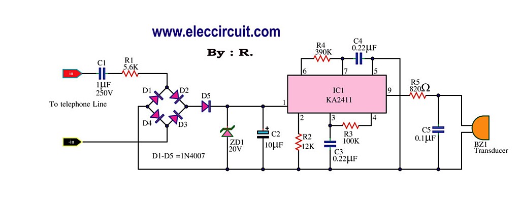
be too tedious. Then came the dial tone method using electronics and computer to connect, eliminating the needs of manual phone line connection. Basically on the caller side, it is a dial tone generator. When a key is being pressed on the matrix keypad, it generate a unique tone. For example, if the key `1` is being press on the phone, the tone you hear is actually consist of a 697hz + 1209hz sine wave.
Pressing key `9` will generate the tone form by 852hz + 1477hz. The frequency use in the dial tone system is of audible range suitable for transmission over the telephone cable. On the telephone exchange side, it has a decoder circuit to decode the tone to digital code. For example, the tone of 941hz + 1336hz will be decoded as binary `1010` as the output. This digital output will be read in by a computer, which will then act as a operator to connect the caller`s telephone line to the receiving telephone line.
The telephone exchange center also generate a high voltage to the receiving telephone, so as to ring the telephone bell, notifying the receiving user. The project below, focus on building a decoder. This circuit can be interface to a computer, allowing caller to computer interaction. Application can be for example be a computerize call receiving/diverting phone network system. Home/Office electrical appliances remote through telephone. Wireless remote control. 🔗 External reference
Related Circuits
This circuit is designed to generate a loud ringing tone for an electricity bell in older telephones. It serves as a replacement for the original ringer, which may be lost, eliminating the need for a new phone. The circuit...
This circuit is a melody generator circuit diagram controlled by the UM66 IC. The UM66 is a CMOS IC designed for applications such as call bells, telephones, and toys. It features a built-in ROM programmed to play music and...
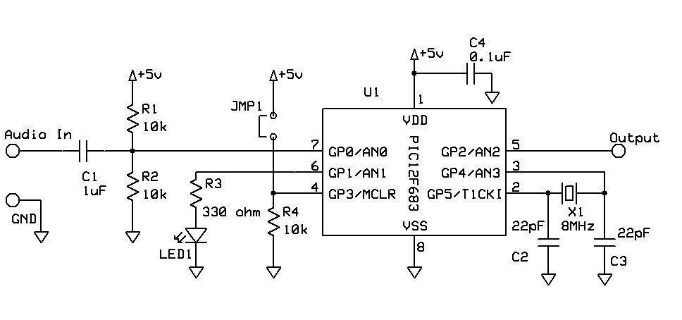
DTMF Touch Tone Decoder Using Microchip PIC Microprocessor. This project contains the details of using a Microchip PIC12F683 8-bit microprocessor to detect Dual-Tone Multi-Frequency (DTMF) signals. The DTMF Touch Tone Decoder circuit utilizes the Microchip PIC12F683 microprocessor, which is an...

This is a simple water level alarm circuit made using a 555 timer IC. The circuit will produce an alarm when the water level reaches a preset level. The water level alarm circuit utilizing a 555 timer IC is designed...
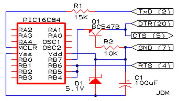
Affordable PIC Programmer. This programmer is compatible solely with the PIC16F84 microcontroller. It is reliable, as it rarely encounters errors, and functions well with nearly all computer systems, in contrast to some alternatives. The PIC programmer designed for the PIC16F84...
This weblog focuses on electronic circuit schematics, PCB design, DIY kits, and electronic project diagrams. It discusses a 32.768 kHz square wave generated by a common watch crystal. This output can be connected to a 15-stage binary counter to...