
Dtmf Generator At90s4414

The described controller system is designed to efficiently manage the operation of a 200 W, 24 V Brushless DC motor, which is commonly used in electric bike applications. The Z8FMC16100 MCU serves as the central processing unit, executing control algorithms that optimize motor performance while ensuring safe operation.
The PWM module within the MCU is critical for controlling the motor's speed and torque. By generating precise PWM signals, the system can adjust the voltage and current supplied to the motor, allowing for smooth acceleration and deceleration. The inclusion of dead-band operation prevents simultaneous conduction of complementary outputs, reducing the risk of shoot-through conditions that could damage the motor driver circuitry.
For safety and reliability, the controller incorporates robust fault protection mechanisms. The over-voltage and over-current protection features monitor the electrical parameters in real-time, triggering protective actions if thresholds are exceeded. Thermal protection further enhances system safety by preventing overheating, which could lead to component failure.
The analog-to-digital conversion capabilities of the MCU enable continuous monitoring of critical parameters such as voltage, current, and back-EMF. This data is essential for implementing regenerative braking, where kinetic energy is converted back into electrical energy during deceleration, improving overall system efficiency.
Additionally, the presence of dual-edge interrupts allows for responsive handling of events, such as changes in motor load or sensor inputs. The 16-bit Timer facilitates accurate timing operations, essential for synchronizing the Hall-effect sensor signals, which provide feedback on the rotor position for precise commutation control.
Overall, this controller design combines advanced microcontroller features with essential safety and performance capabilities, making it well-suited for electric bike applications that require efficient and reliable motor control.This application note describes a controller for a 200 W, 24 V Brushless DC (BLDC) motor used to power an electric bike. The design uses Zilog`s Z8 Encore! MC Z8FMC16100 Microcontroller unit (MCU) and associated circuitry to implement motoring control, regenerative braking, and fault protection.
Protection Logic for over-voltage, over-cur- ren t, and thermal protection. Discussion The Z8FMC16100 Series Flash MCU features a flexible Pulse Width Modulation (PWM) module with three complementary pairs or six independent PWM outputs supporting dead-band operation and fault protection trip input. These features provide multiphase control capability for a variety of motor The Z8FMC16100 Series MCU features up to eight single-ended channels of 10-bit analog-to- digital conversion (ADC), with a Sample and Hold circuit.
It also features one Operational Amplifier for current sampling and one Comparator for over- current limiting or shutdown. A high-speed ADC enables voltage, current, and back-EMF sensing, while dual-edge interrupts and a 16-bit Timer provide a Hall-effect Sensor inter- face.
🔗 External reference
Related Circuits
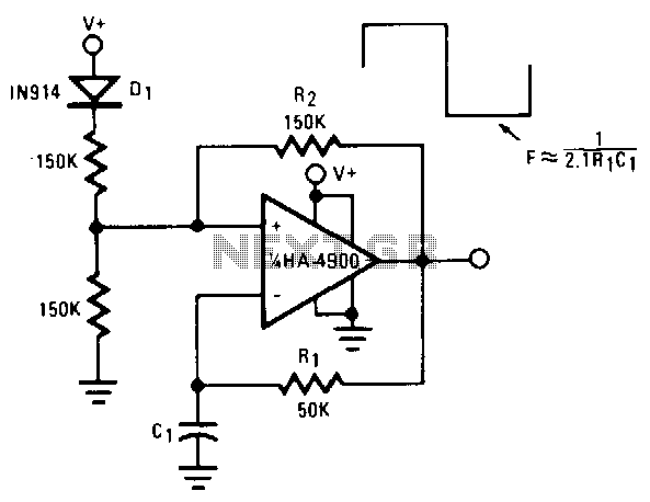
This self-starting fixed-frequency oscillator circuit provides excellent frequency stability. R1 and C1 form the frequency-determining network, while R2 delivers the regenerative feedback. Diode D1 improves stability by compensating for the difference between VaH and VsurrLY. In applications where a...
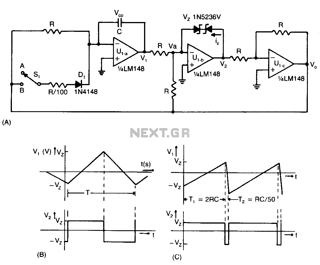
This low-cost operational amplifier circuit (A) generates four different functions with adjustable periods. For the components shown here, the period of the output waveforms is given by T = 4RC and T = 2RC. When switch SI is in...
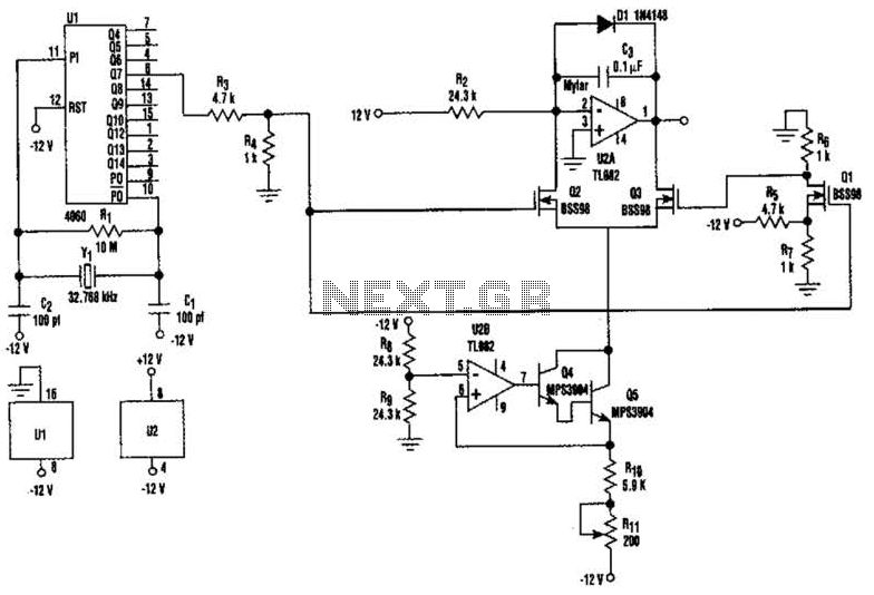
U2-a, U3, and R2 function as an integrator. Q2 and Q3 are alternately switched at 256 cycles. U2-b, Q4, Q5, and R8 through R11 form a constant current generator, with R11 configured to produce a symmetrical triangular waveform. The circuit...
A versatile circuit of an IF signal generator that may be of interest to radio hobbyists and professionals alike. Transistors T1 and T2 form an astable multivibrator oscillating in the audio frequency range of 1 to 2 kHz. An...
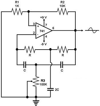
This circuit generates a sine wave using a single operational amplifier (741). The feedback loop of the op-amp includes a twin-T filter connected between its output and inverting input. Positive feedback for oscillation is provided by resistor R2. The...
The timing must be exact to get those high voltage spikes. I used a tiny magnet on the rotor, that triggered a reed switch allowing the relay to pulse the energy from the recovery coil to the primary battery....