
Dual ignition coil driver

The ignition coil serves as an essential component in generating high voltage for spark production in internal combustion engines. Its operation is based on electromagnetic induction, where the primary winding, when energized, creates a magnetic field that induces a high voltage in the secondary winding due to the high turns ratio. The quality of insulation is crucial, as any breakdown can lead to inefficiencies or damage. The design of the ignition coil, typically featuring a laminated iron core to minimize eddy currents, enhances performance by allowing rapid magnetic field changes necessary for high voltage generation.
In experimental setups, especially those utilizing older ignition coils, safety precautions should be paramount. The connection of coils in anti-parallel through a mains sine-wave chopper requires careful consideration of the circuit design to prevent electrical hazards. The choice of components, such as the thyristor for controlling the waveform, should be made with an understanding of the electrical characteristics and limitations of the ignition coils being used. Additionally, the use of capacitors for current limiting is essential to protect the coils from excessive current that could lead to overheating or failure.
When experimenting with high voltage systems, the risk of electrical arcing must be addressed through proper insulation techniques and materials. The selection of insulating materials should consider their dielectric strength and thermal properties to ensure reliable operation under high voltage conditions. Overall, the innovative use of automotive ignition coils in high voltage applications showcases their versatility and the potential for creative experimentation in electronics.Apart from flyback transformers or MOTs, automotive ignition coils are also used as high voltage sources by many enthusiasts. Especially those classic cylinder-shaped ones, used in carbureted engines pre-1990, since these were driven directly from the battery (through contact breakers) to generate sparks and a sturdy primary/secondary winding with
appropriate insulation had to be met. Now, whether you have the old one or today`s modern coils, the principle stays the same. Any ignition coil is basically a special iron-cored transformer with an open magnetic loop and a high sec/pri turns ratio, with its HV return pin permanently connected to the primary. This setup is then submerged in oil, or dipped in any similar insulation material, like asphalt or concrete and hermetically sealed.
Most ignition coils as of today are way smaller, since these are driven through your car`s electronic ignition system. For experimentation however, I recommend the former type. My approach how to drive these two (came from a SKODA 120 ) was in anti-parallel through a mains sine-wave chopper, like a light dimmer, similar to my triac phase regulator circuit.
To chop the waveform I`ve chosen a thyristor (SCR) instead of the TRIAC, as we don`t need full-wave control, it`d introduce more stress on the coils. Since the high voltage return output is always connected to the primary, driving two coils this way presents a drawback: the whole circuit, including HV outputs, is on mains potential.
The only way how to get HV against ground from this setup is to drive only one coil, making sure that your second primary connection (the one which is connected to HV secondary) is always earthed. For those unlucky ones with a TN-S (separated neutral and PE), or even with ground fault circuit interrupters, this might not be possible at all without using an external insulation 1:1 mains transformer, since you cannot draw current between live and PE.
But what high voltage experimenter has a GFCI installed in It would drive him nuts. Simple, isn`t it Mains with light dimmer in series, potentiometer regulates SCR`s conduction angle; two run capacitors (for current limiting) and two ignition coils in out of phase. I`d recommend lower capacities if you do have those modern coils, though. And because it runs straight off mains frequency, the sparks have a loud distinct growl totally incomparable to my flyback drivers.
Because a two-coil setup, such as this one, greatly exceeds the output voltage ranges your ignition coils were designed to operate in, you might be plagued with arc-overs to the primary. Don`t let it burn a conductive trace once the sparks alone aren`t as powerful as flyback arcs, nevertheless use any good insulating material such as glass, silicone, hot glue or rubber to see if it helps.
🔗 External reference
Related Circuits
The interface uses a PIC16F876 microcontroller and not much else. It performs channel mixing, current limiting, and noise rejection. Push the stick forward, both motors move forward, move the stick to the left and the robot moves left. It...

This relay driver enhances the input impedance using a standard BC547 NPN transistor (or its equivalent). It is a widely used driver capable of operating various relays, including reed relays. Transistors Q1 and Q2 function as a simple common-emitter...
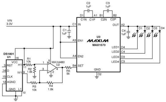
This white LED driver circuit operates up to four white LEDs in parallel from a 3.3V power source, adjusting the total LED current from 1mA to 106mA in 64 steps of 1dB each. The brightness control of the LEDs...
A very popular circuit for driving DC motors (ordinary or gearhead) is called an H-bridge. It's called that because it looks like the capital letter 'H' on classic schematics. The great ability of an H-bridge circuit is that the...
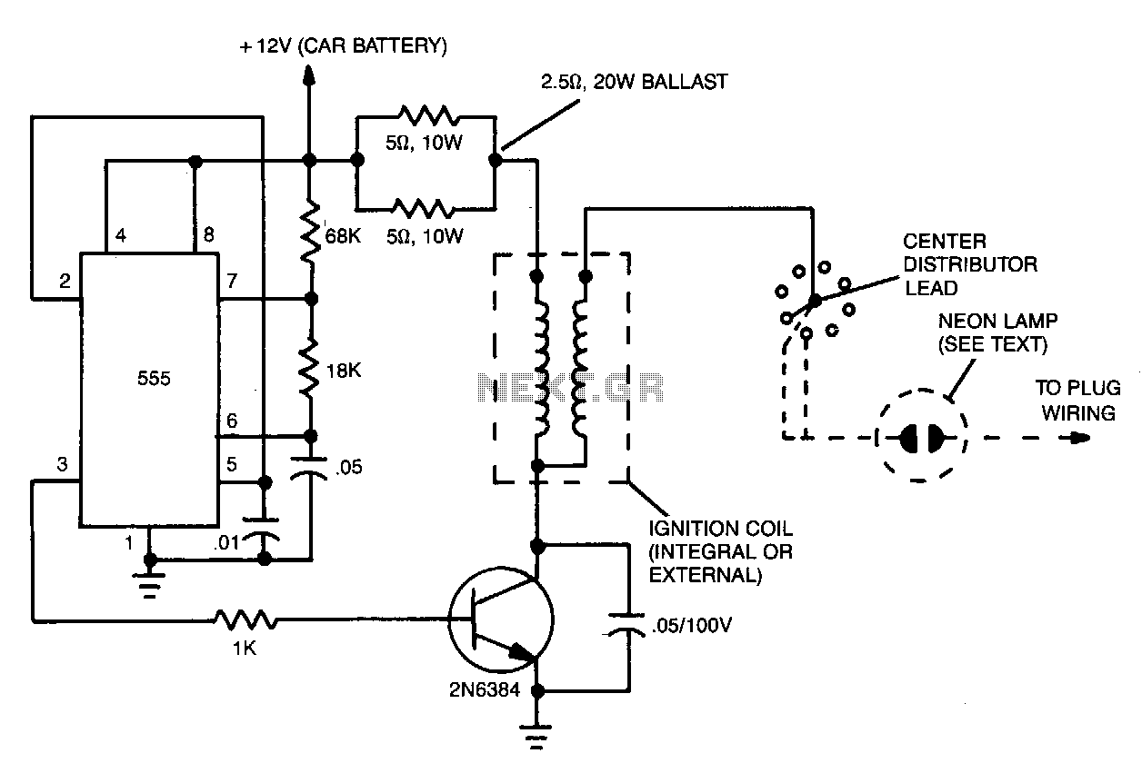
The ignition substitute provides a constant power source for the ignition coil. Its frequency, 0.5-1.0 kHz, is that used by an 8-cylinder engine with an idling speed of 650 RPM, and the unit provides a rapid spark at a...
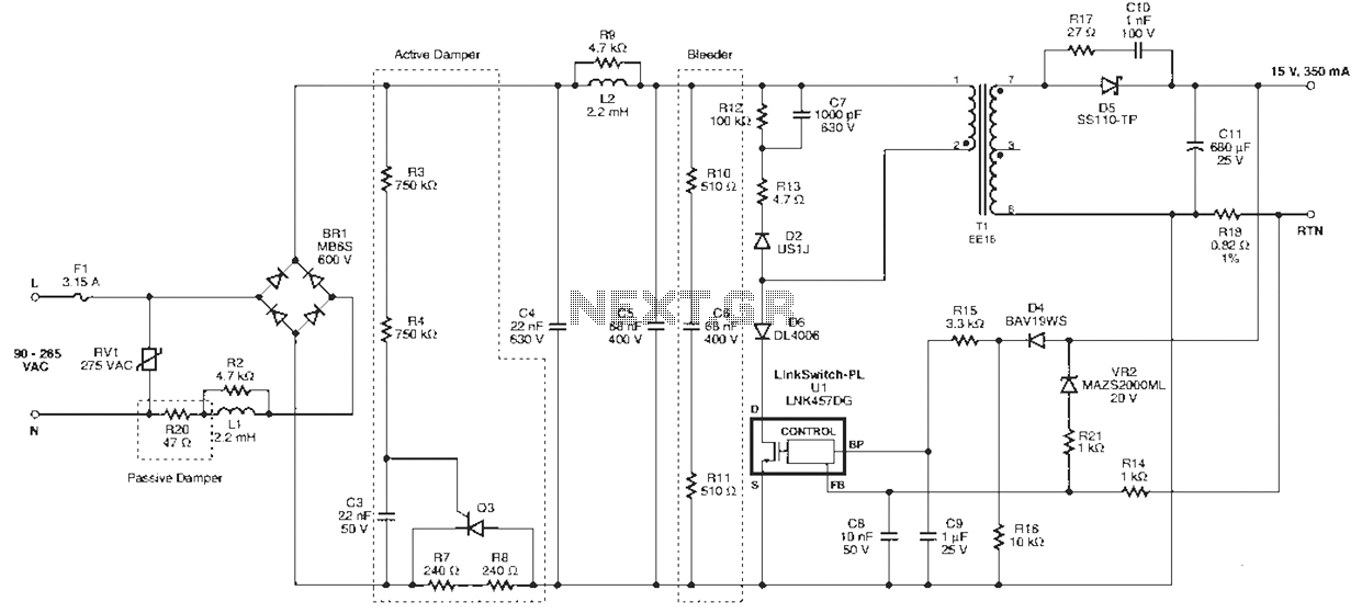
Power Integrations' DER322 reference design employs the LinkSwitch-PL family of LNK460VG devices. This design represents the industry's first alternative 100W A19 incandescent LED driver utilizing a single-layer PCB. It is characterized by low cost, minimal component count, and compact...