
led flashing circuit
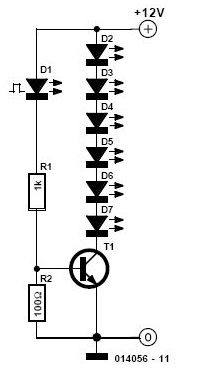
This circuit operates as an astable multivibrator, which is a fundamental configuration for generating square wave signals. The continuous oscillation between the two states is created by the feedback mechanism established through the two transistors, T1 and T2. When one transistor turns on, it drives the other into a cutoff state, creating a rapid switching effect that results in the flashing of the LEDs.
The timing characteristics of the circuit are primarily determined by the values of the resistors and capacitors connected to the transistors. The potentiometer P1 allows for the adjustment of the timing, providing control over the frequency of the LED flashing. A lower resistance or capacitance value will yield a faster oscillation frequency, leading to quicker transitions between the on and off states of the LEDs.
The circuit's design is robust, allowing for the use of various small-signal transistors, such as the BC238, provided that they have similar characteristics to the BC547B. This flexibility in component selection ensures that replacements can be made without significantly affecting circuit performance. However, it is crucial to ensure that both transistors are functioning correctly, as a failure in either component can disrupt the oscillation and diminish the circuit's overall functionality.
The circuit is designed to operate effectively at a nominal voltage of 9 volts, making it suitable for a variety of applications. Lower operating voltages can also be utilized, which may require recalibration of the resistors to maintain the desired flashing frequency. The use of red LEDs is standard in this design, but the circuit can be adapted to accommodate different colors by adjusting the series resistors R1 and R4, which control the current flowing through the LEDs, thus allowing for a range of visual effects based on the selected LED color.It`s state is constantly changing and this change affect the flow of current and voltage and the effect will be visible with the two leds. The speed of the led flasher may be adjusted with potentiometer P1. Being an astable multivibrator, the circuit has no stable state but oscillates continuously between the two states back and forth.
The two transistors T1 and T2 turn and lock each other by turn. The smaller the capacitor value is and the smaller the resistance, the appropriate LED goes out faster, for the benefit of other, who then immediately turns on. The transistors do not necessarily have to be BC547B, you may use BC238 or similar small-signal transistors.
It is recommended to always use the equivalent transistors. If one of the transistors is defective, wrong or have a malfunction, so does this to the full functionality of this circuit. One LED lights up and the other is dimmed. The two flashing led circuit is designed for 9 Volts but it works at lower voltages too. In this design we used red leds but by changing the series resistors R1 and R4 you can also use different LED colors.
🔗 External reference
Related Circuits
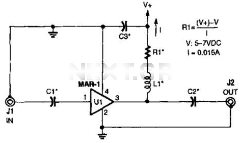
The low-cost Mini-Circuits MAR-X series of chips provides a significant advantage for RF builders, featuring inherent 50-ohm input and output impedances essential for RF systems. An MAR-1-based receiver/scanner preamplifier is illustrated. Capacitors Ci and C2 are chip capacitors, with...

This circuit design for a laser diode driver can be implemented using a voltage-controlled current source. This simple linear laser diode driver provides a cleaner drive current compared to switched (PWM) drivers. The circuit is based on the OPA350...

A dimmer is a simple device used to reduce the brightness of incandescent lamps and to control the speed of collector motors. This concept has gained popularity due to the abundance of outdated Soviet circuits available on Lithuanian internet...

Project with Circuit and Code for a Typing Assistant using the 8051 microcontroller (AT89S52) and the PS/2 keyboard port of a computer. The project also explains the interfacing of the PS/2 port of a computer with the 8051 microcontroller. The...
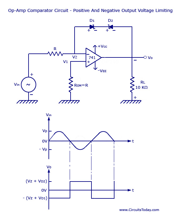
Voltage Limiter Circuit Using Op-amp - Circuit Diagram, Waveform, Positive and Negative Voltage Limiters. The voltage limiter circuit utilizing an operational amplifier (op-amp) serves to restrict the output voltage to predefined levels, effectively preventing it from exceeding or falling below...
One cannot expect high performance from a basic detector-based meter. Its sensitivity is merely sufficient to provide a fundamental understanding of the power output that the transmitter can achieve. The detector-based meter operates on a straightforward principle where it measures...