Water Activated Alarm
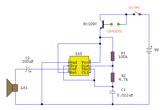
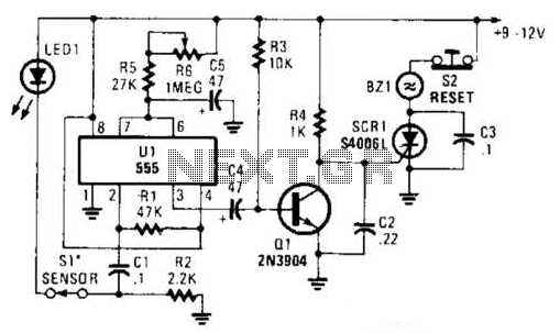
The circuit utilizes a 555 timer configured as an astable oscillator, powered by the emitter current of a BC109C transistor. In dry conditions, the transistor remains off due to the absence of bias current. However, when the probes come into contact with moisture, a small current flows from the base to the emitter, activating the transistor. This activation allows a larger current to flow through the collector circuit, which in turn enables the 555 oscillator to produce sound. An On/Off switch is included in the design, and it is recommended to use non-reactive metals for the probe contacts. Gold or silver-plated contacts from an old relay can be utilized, but an economical alternative is to use alternating copper strips from a piece of veroboard. Although these copper strips may oxidize over time, the minimal current flowing in the base circuit means that the increased impedance from oxidation is not a significant issue. There is no need for a base resistor, as the transistor operates in an emitter follower configuration, with the current limited by the impedance at the emitter, which is part of the oscillator circuit.
The described circuit is a practical application of a 555 timer in an astable mode, where it continuously oscillates between high and low states, generating a square wave output. The BC109C transistor functions as a switch that responds to the moisture detected by the probes. In the absence of moisture, the transistor remains in a non-conductive state, preventing any output from the 555 timer. The transition to a conductive state upon moisture detection allows the circuit to activate, providing an audible signal which can be used for various applications, such as moisture detection in soil or other environments.
The choice of materials for the probe contacts is crucial for maintaining circuit integrity and performance. The use of gold or silver plating is preferred due to their excellent conductivity and resistance to corrosion. However, the alternative of using copper strips is a cost-effective solution, albeit with the potential drawback of oxidation over time. The design compensates for this by ensuring that the circuit can still function effectively even with increased impedance from oxidized contacts.
In terms of circuit implementation, the 555 timer is connected in such a way that it generates a frequency determined by external resistors and capacitors. The timing components must be selected based on the desired frequency of the output signal. The inclusion of an On/Off switch allows for user control over the circuit's operation, enhancing its usability. Overall, this circuit exemplifies a simple yet effective approach to moisture detection, leveraging widely available components to achieve reliable performance.It uses a 555 timer wired as an astable oscillator and powered by the emitter current of the BC109C. Under dry conditions, the transistor will have no bias current and be fully off. As the probes get wet, a small current flows between base and emitter and the transistor switches on. A larger current flows in the collector circuit enabling the 555 osillator to sound. An On/Off switch is provided and remember to use a non-reactive metal for the probe contacts. Gold or silver plated contacts from an old relay may be used, however a cheap alternative is to wire alternate copper strips from a piece of veroboard. These will eventually oxidize over but as very little current is flowing in the base circuit, the higher impedance caused by oxidization is not important.
No base resistor is necessary as the transistor is in emitter follower, current limit being the impedance at the emitter (the oscillator circuit). 🔗 External reference
