
DVR IR Motion Trigger

The circuit design consists of several critical components that work together to ensure proper functionality. The core of the timer is built around U1, which is configured as a monostable multivibrator. The resistor R2 and capacitor C1 form a timing network that determines the duration the DVR remains active after motion is detected. The values of R2 and C1 can be adjusted to set the desired recording time, making the system flexible for various applications.
U2, another timer, acts as a secondary control mechanism. Upon receiving a pulse from the motion detector, U2 initiates a delay of approximately 100 ms before triggering U1. This delay allows the system to filter out noise or false triggers that may occur from brief motion. Additionally, U2 generates a short wake-up pulse through C4, which is crucial for activating the DVR. This pulse is designed to last about 50 ms, which is sufficient for the DVR to recognize the command to start recording.
Diodes D1 and D2 play a vital role in shaping the output signals. They ensure that the wake-up pulse and the longer timing pulse from U1 do not interfere with each other while still allowing both signals to reach the DVR. The output transistor Q3 acts as a switch, controlling the connection to the DVR based on the combined signals from the timer circuits. When a pulse is detected from the IR motion detector, Q1 is activated, allowing C1 to discharge and reset the timer, thus restarting the recording duration.
This circuit provides a robust solution for maintaining DVR recording in response to motion detection, accommodating the need for both initial activation and ongoing recording adjustments based on continuous motion detection. The design can be further refined by selecting appropriate components based on the specific requirements of the DVR and the motion detection system in use.A client needed a timer to keep his DVR enabled and recording when the IR motion detector output a pulse. A timer was required to maintain a low signal level for a precribed amount of time upon detection of motion.
However, it was determined after some experimentation that the DVR ignored singular outputs, and thus required a "wake up" pulse, whic h would not be present when using an ordinary timer configuration. The included circuit allows the client to set the time to record after motion detection in the customary way, using a timer and RC network. And, it provides the necessary wakeup pulse so that the DVR will record for the preset time each time motion is detected.
Additionally, it was required that if motion is detected during the recording process, the recording time would "reset" and began the time interval again for each subsequent output pulse from the motion detector. U1 in the drawing sets the recording time via R2 and C1. Several minutes of recording time can be realized with selecting R2 from a few Megohms to a few tens of Megohms (Note: the value given on the schematic is for simulation only).
Timer U2 has two purposes: It triggers U1 after about 100mS from the time the pulse is detected, via Q1, and also generates a short "wake up" pulse via C4, which is a pulse of about 50mS. Diodes D1, D2 and output transistor Q3 combine the wakeup pulse and the long timing pulse for the DVR.
The connection to the DVR is taken at the collector of Q3. If any pulse is detected from the IR unit, U1 discharges C1 thru Q1, and thus the DVR time is started again from zero. The wake up pulse isn`t forwarded to the DVR in that case. 🔗 External reference
Related Circuits
The Slave Flash Trigger is activated by pressing a push button. When activated, the indicator lamp emits one to three flickers to indicate the programmed mode. One flicker means the flash will fire with each flash, two flickers indicate...

This motion detector alarm is capable of detecting a moving person from a distance of 1 meter. It utilizes a dual IR Transmitter-Receiver module, specifically the HOA1405. The motion detector alarm system operates on the principle of infrared (IR) detection,...
This highly sensitive movement detector is designed using bipolar transistors and operates with a current draw of only 0.3 mA during quiescent conditions. It is primarily intended as a protection device but can also be utilized in specific games....
H-bridge applications for robots, robotics, and motor control. This post focuses on the low-side switch element. H-bridges are widely utilized in robotics and motor control applications to enable bidirectional control of DC motors. An H-bridge consists of four switches arranged...
A typical circuit for welding equipment is illustrated in the following circuit diagram. The turn-on delay can be accurately controlled with Potentiometer P2, allowing for effective discharge management. The welding equipment circuit typically incorporates several key components to ensure proper...
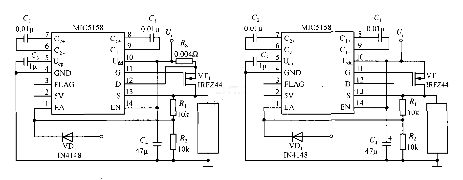
The MIC5158 is part of a high-speed switching circuit diagram that focuses on the rising edge. The MIC5158 is a precision voltage reference and high-speed switching device that is commonly utilized in various electronic applications requiring rapid signal transitions. In...