
Easy Debugging Terminal
The LCD terminal circuit is designed to facilitate two distinct modes of operation for data display, controlled by jumper J1. In the ASCII mode, with J1 open, the terminal interprets and displays incoming serial data as standard ASCII characters, making it suitable for general-purpose text output. This mode is particularly useful for applications that require human-readable data representation.
Conversely, when J1 is closed, the terminal switches to hexadecimal mode, allowing for the visualization of raw binary data in a more compact hexadecimal format. This capability is essential for debugging and analyzing data streams from various serial devices, as it provides a clear representation of the underlying data values without the need for conversion.
The heart of the terminal's functionality is the PIC16F84 microcontroller (IC U2), which handles the processing of incoming serial data and manages the display output. The microcontroller is programmed to interpret the data format based on the selected mode and drive the LCD display accordingly.
Input signals are received through connector K1, which is designed to interface with standard serial communication lines. The terminal can be powered using either a 9V DC adapter or a 9V battery, providing flexibility for both stationary and portable applications. This dual power option ensures that the terminal can be utilized in various environments without being tethered to a fixed power source.
The implementation of jumper J1 allows for easy switching between the two modes, making the terminal versatile for different tasks. The simplicity of the design, combined with the functionality offered by the PIC16F84 microcontroller, makes this LCD terminal a valuable tool for developers and engineers working with serial data communication.This LCD terminal provide two modes of operation by selecting jumper J1. When J1 is open the terminal operate as a normal ascii display terminal, when J1 is closed the terminal displays the input serial data in hexadecimal format. This mode is useful for viewing raw data from the serial port output. IC U2 a PIC16F84 micro controller is used to control the operation of the terminal. Input signal is applied to connector K1. The circuit can be powered either by 9V dc adapter or by using a 9V battery. Jumper J1 select the operating mode of the terminal, J1 open for ascii terminal mode, closed for hexdecimal display mode.
🔗 External reference
Related Circuits
An EEPROM is a type of non-volatile memory, which means it is used for permanently storing digital data without any power supply. EEPROM stands for Electrically Erasable Programmable Read-Only Memory. The advantage of this type of ROM is that...
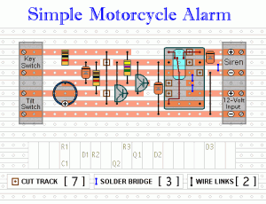
The following circuit is a simple, inexpensive, and easy-to-build motorcycle alarm. The circuit requires only two transistors to drive a relay, which acts as a switch to activate a buzzer. Any number of normally-open switches can be used. Mercury...
This document outlines a simple SWR (Standing Wave Ratio) protection circuit that can be easily constructed. The directional coupler and detector components are sourced from an old VHF SWR meter. It is advisable to replace the existing RF bypass...

The interface circuit is placed between the computer's standard video signal output terminal and the television. It amplifies the standard 1V (Peak-to-Peak) video signal to 3V (Peak-to-Peak). The negative feedback circuit consists of transistors T1 and T2, providing a...
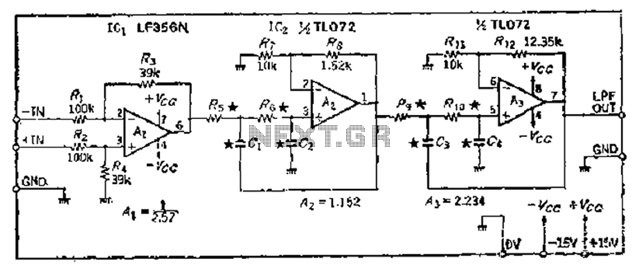
A 24 dB/octave Butterworth filter with a maximally flat characteristic is constructed using two filters, each capable of providing a 12 dB/octave response. This configuration allows for a 3 dB point adjustment. To achieve the desired cutoff frequency, adjustments...
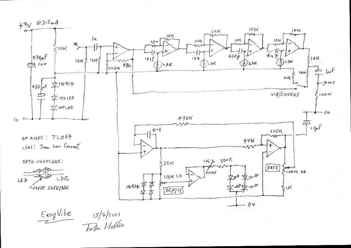
I aimed to copy the sound rather than the vintage circuit. Easy to build, low current consumption, no signal level changes on bypass, quiet and, most importantly, it does that Bridge of Sighs thing. The circuit described focuses on replicating...
Warning: include(partials/cookie-banner.php): Failed to open stream: Permission denied in /var/www/html/nextgr/view-circuit.php on line 713
Warning: include(): Failed opening 'partials/cookie-banner.php' for inclusion (include_path='.:/usr/share/php') in /var/www/html/nextgr/view-circuit.php on line 713