
Echo Tone Oscillator
This circuit operates by using amplitude modulation to create sound waves that mimic the echo characteristics of underwater sonar systems. The core of the circuit consists of a tone generator that produces a continuous wave at a specified frequency, which is then modulated by an envelope generator to simulate the fading and reverberation of sound in water. The pitch control allows the user to adjust the frequency of the generated tone, while the rate control modifies the speed at which the modulation occurs, thus affecting the perceived depth and distance of the echo.
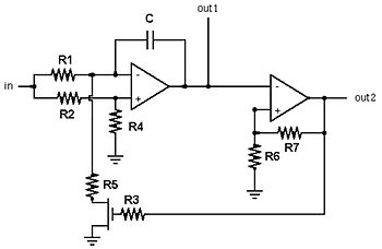
The implementation of integrated circuits (ICs) U1, U2, and U4 plays a crucial role in ensuring the stability and performance of the circuit. These ICs are responsible for generating the necessary waveforms and controlling the modulation process. Proper grounding and short wiring practices are essential to prevent interference and maintain the integrity of the audio output.
To enhance the circuit's versatility, the use of potentiometers for pitch and rate adjustments allows for real-time manipulation of the sound characteristics, enabling users to experiment with different settings to achieve the desired auditory effect. The recommended values for the pitch and rate provide a solid starting point, but users are encouraged to explore variations to suit their preferences or specific applications.
Overall, this circuit serves as an educational tool and a creative platform for sound design, particularly in applications related to model building, audio effects, and hobbyist electronics. Its simple yet effective design allows for a broad range of modifications and enhancements, making it a valuable project for both beginners and experienced electronics enthusiasts.This simple circuit amplitude-modulates a single tone in such a manner to approximate the echo effect one might obtain, for instance, with sonar apparatus. Any reader who has been on a sonar-equipped vessel will realize that some imagination is required to appreciate the similarities among this simple scheme and the "real thing.
" However, this cir cuit might adjunct a small model (of a submarine, perhaps) to add the dimension of sound. Long ago, I was indelibly impressed with myriad sci-fi adventure serials, such as "Voyage to the Bottom of the Sea. " There, a variety of simple audio effects, either provided by tape or phonographic reproduction, or by the most rudimentary laboratory apparatus, created the incidental sounds that gave these episodes an added dimension of reality.
I loved to devise ways of making these sounds on command, and thus designed and constructed a number of appropriate electronic circuits, well represented by this example. The original renditions were entirely made of discrete (usually germanium) transistor arrangements. Later, I converted many of these designs into integrated-circuit equivalents, which both decreased their size (allowing them to fit into pockets!), and their cost.
Lay-out and construction technique is left to the builder. The use of a substantial ground bus and direct, short wiring, is suggested in the area of ICs U1, U2, and U4 and their associated components, to prevent unwanted oscillations. The two major parameters, "pitch" and "rate" may be alternatively made variable by replacing the relevant resistors, RPITCH and RRATE with 250, 000-ohm potentiometers in series with 10, 000 ohm resistors.
I selected the parameters of about 970 hertz for the pitch, and 16 hertz for the clock rate, merely on personal preference, for what seemed to be the best "Science Fiction Coefficient. " Click here for an audio sample of this circuit`s output. 🔗 External reference
Related Circuits
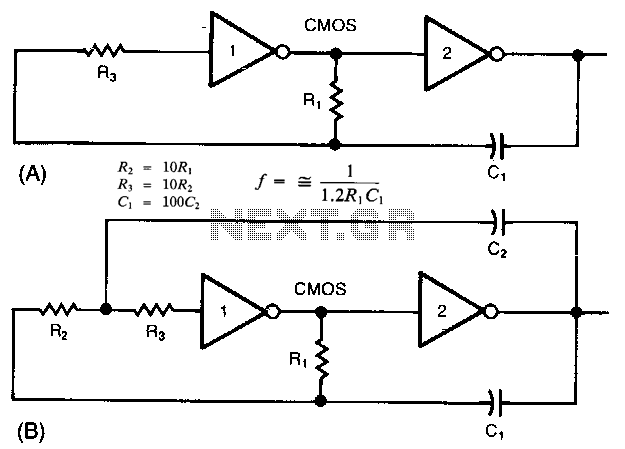
The common clock oscillator illustrated in Fig. 68-19A has two minor issues: it may not oscillate if the transition regions of its two gates differ. If it does oscillate, it might occasionally operate at a slightly lower frequency than...
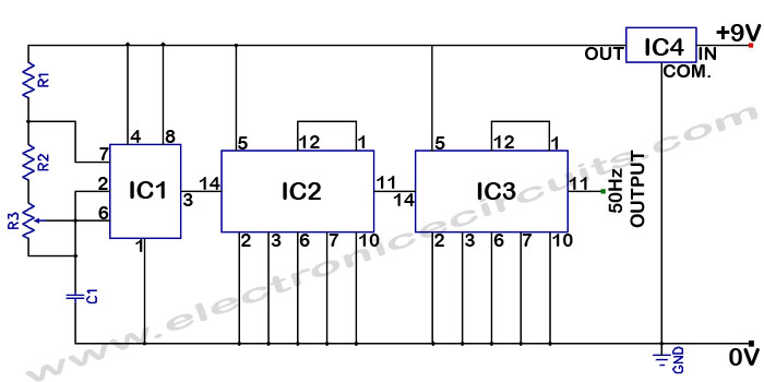
Accurate 50Hz Oscillator Circuit Using 555 and 7490. This circuit generates a 50Hz pulse. It consists of a 555 timer and two 7490 divide-by-ten counters. The circuit utilizes a 555 timer configured in astable mode to produce a square wave...
A tutorial on the Wien Bridge Oscillator circuit, which utilizes an RC phase shift oscillator to generate sine waves. The Wien Bridge Oscillator is a well-known electronic circuit used to produce sine waves. It operates based on the principle of...
A voltage-controlled oscillator is an oscillator whose frequency of oscillation can be varied by changing an applied voltage. A voltage-controlled oscillator (VCO) is an essential component in various electronic systems, particularly in communication devices, signal processing, and modulation applications. The...
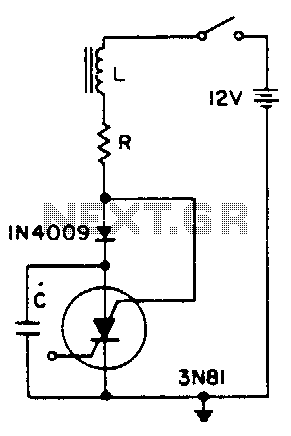
A positive transient, such as the power switch closing, charges through L to a voltage above the supply voltage, if Q is sufficient. When the current reverses, the diode blocks and triggers the SCS. As the capacitor discharges, the...
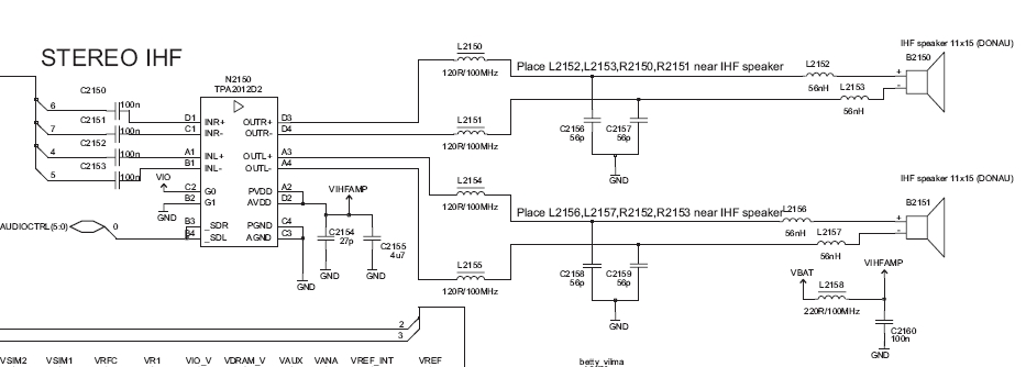
Before proceeding with these steps, ensure that the software calibration and the basic procedures for checking audio circuit components have been completed. The audio circuit schematic diagram is preferred for easy tracking, and this method will aid in future...
Warning: include(partials/cookie-banner.php): Failed to open stream: Permission denied in /var/www/html/nextgr/view-circuit.php on line 713
Warning: include(): Failed opening 'partials/cookie-banner.php' for inclusion (include_path='.:/usr/share/php') in /var/www/html/nextgr/view-circuit.php on line 713