
Economical Crystal Time Base

The described time base circuit employs a crystal oscillator as its frequency source. The crystal, tuned to 3.2768 MHz, serves as a stable frequency reference. The circuit utilizes frequency division techniques to achieve the desired output frequencies of 50 Hz, 100 Hz, and 200 Hz. This is typically accomplished using a series of flip-flops or counters that divide the input frequency down to the required output frequencies.
The power supply specifications of 5 to 15 V indicate that the circuit is designed for versatility, allowing it to be integrated into various systems that may operate at different voltage levels. The current requirement of 0.05 to 2.5 mA suggests that the circuit is energy-efficient, making it suitable for battery-operated devices and low-power applications.
In terms of components, the circuit may include resistors, capacitors, and possibly additional integrated circuits (ICs) for signal conditioning and output buffering. The output stage may involve transistors or logic gates to ensure the generated signals are compatible with other digital circuits or microcontrollers.
Overall, this time base circuit is a practical solution for generating precise timing signals in a variety of electronic applications, benefiting from the stability of the crystal oscillator and the efficiency of its design. The above time base circuit will provide 50-, 100-, or 200-Hz signals from an inexpensive crystal cut for 3.27 6 8 MHz, a common crystal used for microprocesser works. It requires a power supply of 5 to 15 V at 0.05 to 2.5 mA.
Related Circuits
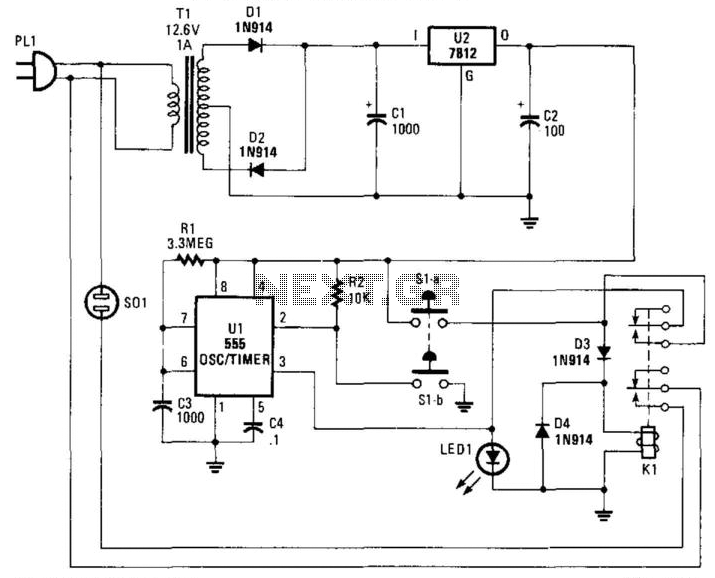
Suitable for cutting off an appliance or other AC load, this timer will cut the AC power after a period determined by R1/C3, as shown, for about 40 minutes. K1 is a relay that should handle about 10 A....
The two circuits demonstrate the process of opening a relay contact shortly after the ignition or light switch is turned off. The capacitor becomes charged, and the relay remains closed until the voltage at the diode anode reaches +12...
With switch SI in the off position, battery voltage is applied across timing capacitor CI, which remains charged while the rest of the circuitry is powered off. Transistor Q1, and consequently transistors Q2 through Q4, remain in an off...
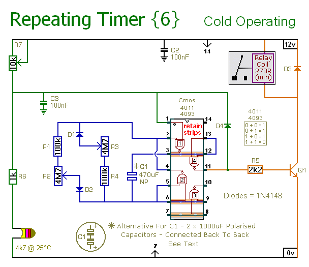
This circuit operates in contrast to Repeating Timer No.5. It activates only when the temperature drops below a predetermined level. The variable resistor (preset) allows for the selection of the temperature threshold at which the timer will become operational. The...
Circuit of a crystal-controlled FM transmitter. The circuit utilizes a crystal oscillator and several power amplifier stages to enhance output power. The crystal-controlled FM transmitter circuit is designed to generate frequency-modulated signals with high stability and precision. At the core...

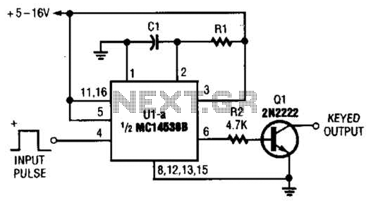
The following method allows the timer to be triggered by a normally closed switch. This would be useful in applications such as intrusion alarms where the protection circuit is broken if a window or door is opened. Trigger Input...