
Economy radar detector
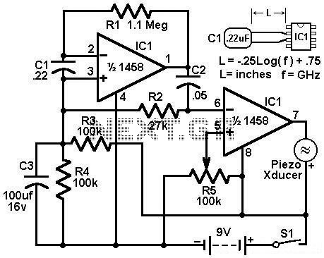
The economy radar detector circuit is designed to detect radar signals effectively using a 1458 dual operational amplifier (op-amp) configuration. The circuit employs a capacitor, designated as C1, which acts as the radar signal detector. This capacitor is crucial for capturing the incoming radar signals and converting them into a usable electrical signal.
The first op-amp in the configuration is utilized as a current-to-voltage converter. This stage is essential for transforming the current output from C1 into a corresponding voltage signal, which can then be processed further. The op-amp's feedback mechanism ensures that the output voltage accurately reflects the radar signal's intensity, allowing for precise detection.
Following this, the second op-amp serves as a buffer for the output from the first stage. This buffering action is vital for isolating the signal and preventing any loading effects that might distort the output. By providing high input impedance and low output impedance, the buffer stage ensures that the signal maintains its integrity as it is sent to subsequent stages of processing or output devices.
The overall design of the economy radar detector circuit emphasizes simplicity and efficiency, making it suitable for applications that require basic radar detection without the complexity of more advanced systems. Proper implementation of this circuit can yield reliable performance in detecting radar signals, contributing to various electronic applications.Economy radar detector Circuit diagram This circuit uses a 1458 dual op-amp to form a radar detector. C1 is the detector of the radar signal. The first op-amp forms a current-to-voltage converter and the second op-amp buffers the output to.. 🔗 External reference
Related Circuits
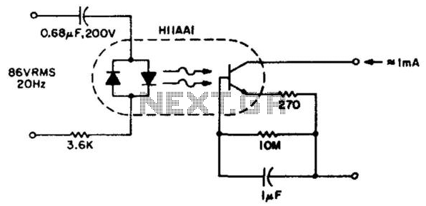
This circuit detects the approximately 20-Hz, 86-Vrms ring signal on telephone lines and initiates action in an electrically isolated circuit. Typical applications include automatic answering equipment, interconnect/interface systems, and key systems. The detector is designed to be simple and...
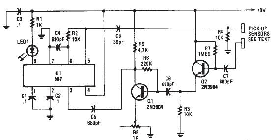
A simple proximity detector electronic project can be designed using this schematic circuit. This project utilizes a tone decoder integrated circuit (NE567), which provides a signal with a frequency of approximately 100 kHz. When an object is placed near...

This liquid detector circuit diagram is designed using common electronic components. The liquid detector can activate an active buzzer to produce sound when a certain water level is reached. Since the water sensor and control circuit for the buzzer...
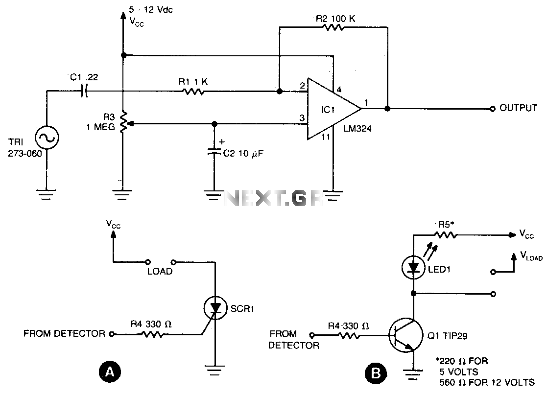
The sensing circuit is designed to detect both steady and fluctuating air flows. It utilizes a Radio Shack piezo buzzer (P/N 273-060) as its core component, along with an LM324 quad op-amp. The red wire from the piezo element...
The detector circuit consists of a two-amplifier multiple feedback bandpass filter followed by an AC-to-DC detector section and a Schmitt Trigger. The bandpass filter, with a quality factor (Q) greater than 100, allows only 500 Hz inputs, which are...
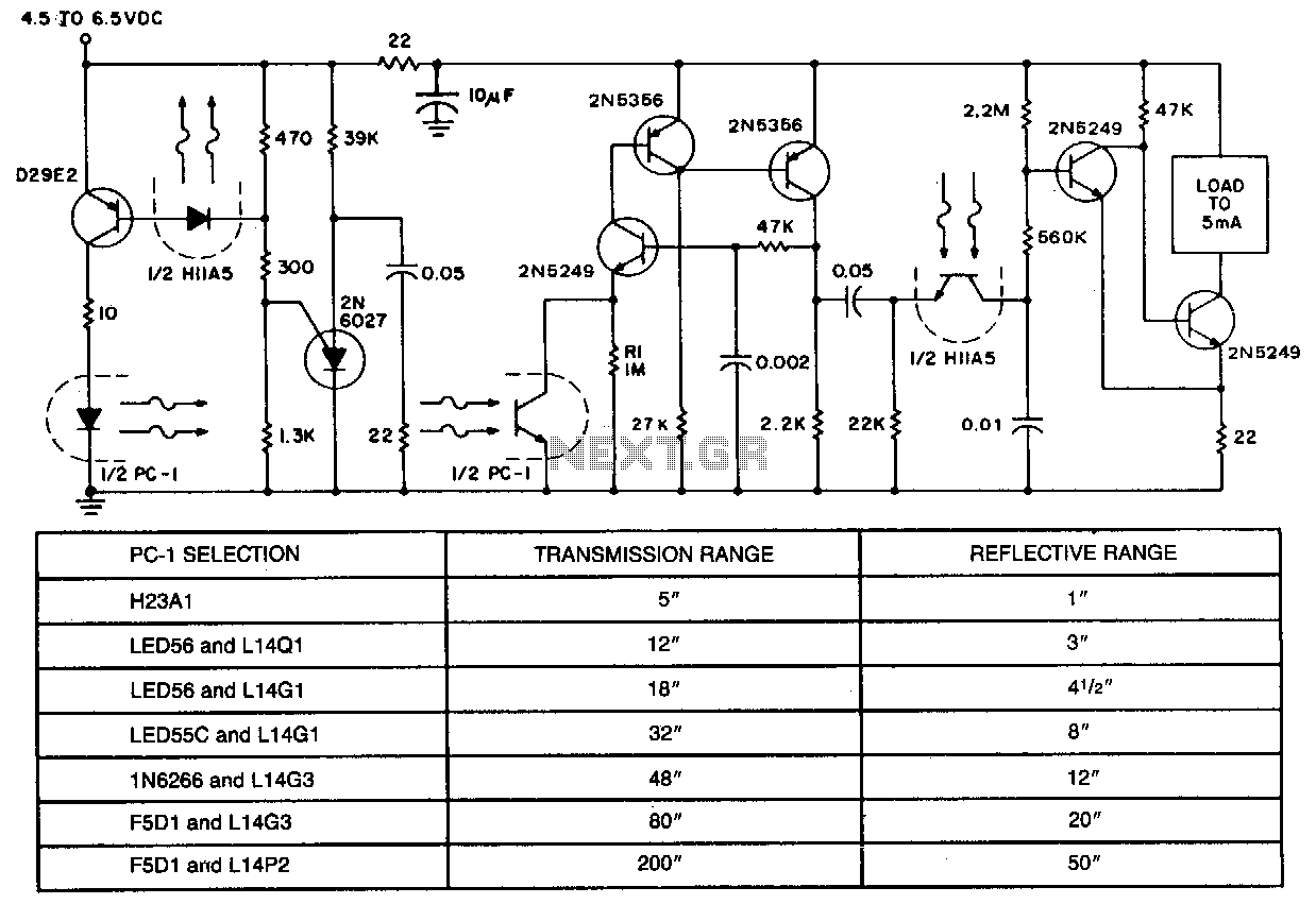
In applications requiring long-range operation with infrared (IR) light sources and high system reliability, pulsed-mode operation of the IR source is essential. Enhanced operational reliability is achieved through synchronous detection of the photodetector current, as implemented in this circuit....