
proximity detector schematic

The proximity detector circuit operates by utilizing the NE567 tone decoder, which is sensitive to a specific frequency. The circuit is designed to detect changes in capacitance caused by the presence of an object within its proximity. The NE567 is configured to respond to a frequency of around 100 kHz, which is generated by an oscillator circuit included in the design.
The sensor component typically consists of two conductive plates that form a capacitor. As an object approaches, the capacitance between these plates increases due to the dielectric effect of the object. This change in capacitance alters the frequency of the oscillator, allowing the NE567 to detect the presence of the object.
Transistors Q1 and Q2 serve as amplifiers in the circuit. They are configured to amplify the output signal from the sensor before it reaches the NE567. This amplification is crucial for ensuring that the signal is strong enough for the tone decoder to accurately process it. The output from the NE567 is then used to drive an LED (LED1), which visually indicates the detection of an object. When the circuit is activated, and an object is detected, LED1 will glow, providing a clear indication of proximity.
This circuit is useful for various applications, such as automatic lighting systems, security alarms, or interactive devices, where the detection of nearby objects is necessary. The simplicity of the design makes it accessible for hobbyists and educational purposes, while still demonstrating fundamental principles of electronics and sensor technology.A very simple proximity detector electronic project can be designed using this schematic circuit. This proximity detector electronic project use a tone decoder integrated circuit ( NE567 ) that will provides a signal with a frequency about 100Khz. When an object is placed near the sensor, the capacitance between sensor is increased. The Q1 and Q2 transistors will amplify the signal and fed it to the NE567 IC, that will make the LED1 to glow. 🔗 External reference
Related Circuits
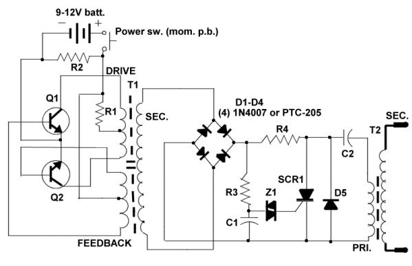
Three schematics are available for individuals interested in constructing their own stun gun. For those familiar with reading electronic schematics, the three stun gun circuits presented on this page contain all the necessary information to build a stun gun....
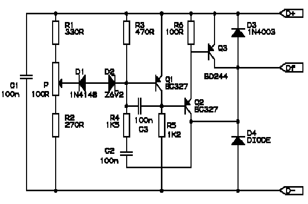
Correctly adjusted, the voltage on the pot wiper is slightly less than half D+ (appx. 0.47*D+) and Q1 will conduct if (D+)-(Vp) > 6.2 + 0.7 + 0.7, or 0.53*(D+) > 7.6V, (D+) > 14.3V. If D+ is lower...
A schematic for a 16-channel passive summing mixer has been developed based on information gathered from various forums and online resources. The 16-channel passive summing mixer is designed to combine multiple audio signals into a single output while maintaining the...
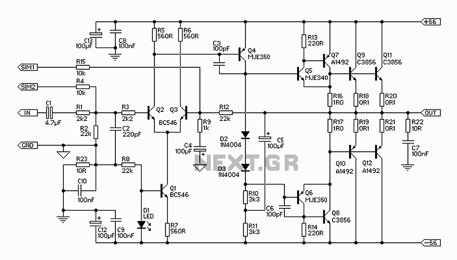
The 300W amplifier circuit presented is a conventional design. It includes connections for the internal SIM and incorporates filtering for RF protection (R1, C2). The input is facilitated through a 4.7µF bipolar capacitor, which offers substantial capacitance in a...
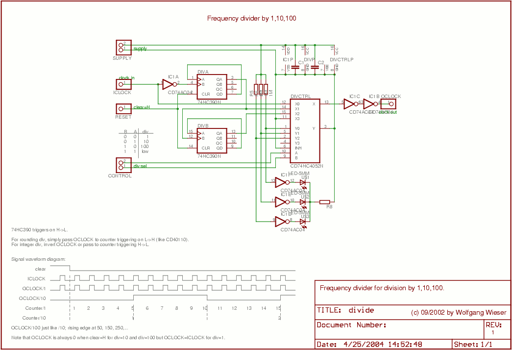
The divider design is straightforward. Users can select a division factor of 1, 10, or 100, or opt for no output (tied low) through the CONTROL input connected to the analog multiplexer HC4052. The design utilizes AC04 to drive...
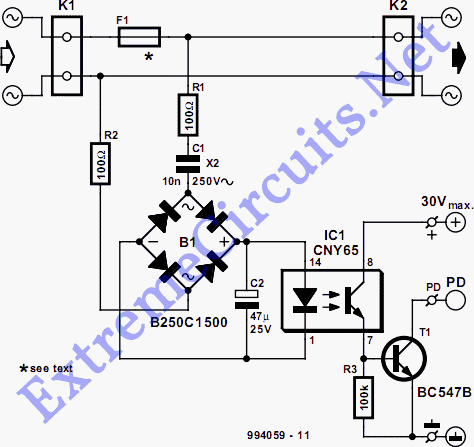
The detector is designed to sense and signal to another circuit when an appliance is connected to the mains voltage. An optocoupler, identified as IC1 in the circuit, is utilized for this purpose. The light-emitting diode within the optocoupler...