
Air-motion detector
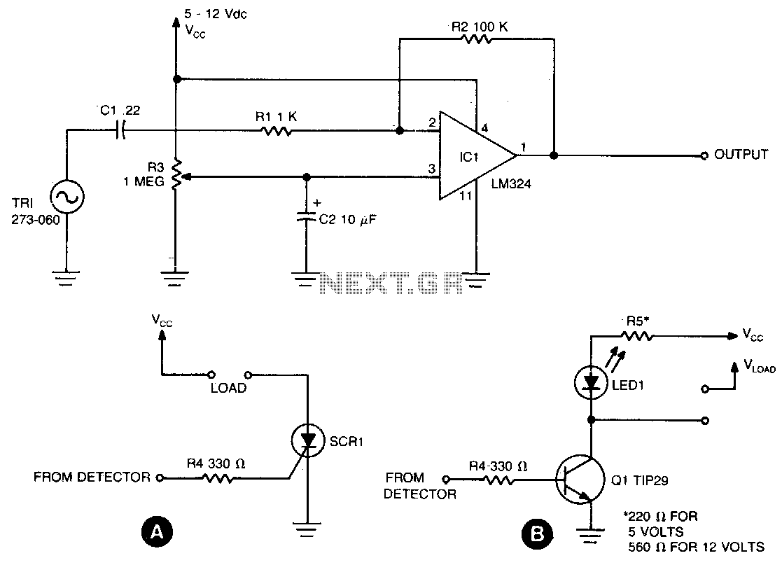
The circuit can be finely tuned to detect subtle movements, such as the wave of a hand, or set to a lower sensitivity where even a strong blow on the element results in no output. Resistor R2 is utilized to adjust the output voltage level at pin 1. This detector circuit can be applied in various control applications. For instance, a silicon-controlled rectifier (SCR) can be implemented to manage 117-volt AC loads, as illustrated in schematic A. Additionally, an NPN transistor like the TIP29 can be used for load control, as shown in schematic B.
The sensing circuit operates by converting mechanical vibrations from air flow into an electrical signal. The piezo buzzer acts as a transducer, converting the kinetic energy of air movement into a voltage signal. The capacitor C1 serves to filter and smooth the signal before it reaches the op-amp, ensuring that only significant changes in the signal are amplified. The LM324, being a quad op-amp, allows for multiple configurations and uses, making it versatile for various applications.
The sensitivity adjustment via R3 allows the user to calibrate the circuit based on the specific environment or application requirements. This feature is particularly useful in applications where the detection of minor air movements is necessary, such as in security systems or automated control systems.
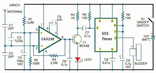
The output from pin 1 of the LM324 can interface with various types of loads. The SCR option provides a means to control high-voltage AC loads, suitable for applications like lighting control or motor operation. In contrast, using an NPN transistor like the TIP29 enables the control of lower voltage DC loads, making the circuit adaptable for different types of devices. Overall, this sensing circuit offers flexibility and reliability in air flow detection and control applications.Sensing circuit detects either steady or fluctuating air flows. The heart of the circuit is a Radio Shack piezo buzzer (P/N 273-060) and an LM324 quad op amp. (Red wire from the piezo element connects to capacitor CI, and the black wire to ground) When a current of air hits the piezo element, a small signal is generated and is fed through CI and R1 to the inverting input (pin 2) of one section of the LM324. That causes the output (pin 1) to go high. Resistor R3 adjusts sensitivity The circuitcan be made sensitive enough to detect the wave of a hand or the sensitivity can be set so low that blowing on the element hard will produce no output. Resistor R2 is used to adjust the level of the output voltage at pin 1. The detector circuit can be used in various control applications. For example, an SCR can be used to control 117-volt AC loads as shown in A. Also, an NPN transistor, such as a TIP29, can be used to control loads as shown in B. 🔗 External reference
Related Circuits
This is a simple and easy-to-build gold detector circuit. The circuit is capable of sensing gold, metal, or coins from a distance of approximately 20 cm, depending on the size of the object being detected. It oscillates at around...

A gas sensor (from Allegro Electronics, Cornwall Bridge, CT06754 Ts GS823) activates in the presence of explosive gas. U5 functions as a voltage-to-frequency converter, with the sensor producing a frequency that is proportional to conductance. The output frequency varies...

This is a linear frequency modulation (FM) detector circuit. This circuit is commonly utilized in telemetry applications and a wide range of analog communication systems. The primary component of this circuit... The linear FM detector circuit is designed to demodulate...
Flame, gas, and smoke detector for fire alarm. This circuit can be combined with an alarm circuit. The output will be a relay that activates and deactivates the alarm. The diagram above illustrates the flame detector. The circuit diagrams...
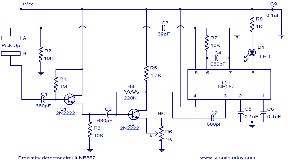
A simple proximity detector circuit utilizing the NE567 integrated circuit (IC). The circuit activates an LED when an object approaches the sensor. The NE567 is a versatile phase-locked loop (PLL) device commonly used for applications such as proximity detection due...
This electronic schematic allows for the design of a simple cellular phone detector circuit capable of sensing the presence of an activated mobile phone from a distance of 1.5 meters. The capacitor C3 should have lead lengths of 18...