
Eggs warming control circuit
The circuit employs a DC power supply that converts 220V AC into a stable DC output, essential for powering various components. The buck converter efficiently reduces voltage while minimizing heat generation. The rectification and filtering stages ensure that the output is smooth and free of ripple, critical for sensitive electronic circuits. The temperature control utilizes a negative temperature coefficient (NTC) thermistor, which provides a precise voltage drop corresponding to temperature changes, allowing for accurate monitoring and control of the incubator environment.
The control logic is implemented using an astable multivibrator configuration with the integrated circuit (IC2), which coordinates the operation of the motors and heating elements based on temperature feedback. The relay (K2) serves as a switching mechanism to control high-power components, ensuring that the low-power control circuit remains isolated from high voltage. The use of limit switches enhances safety by preventing mechanical overload and ensuring that the system operates within designated parameters.
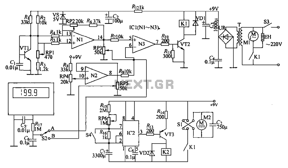
Furthermore, the adjustable resistors (potentiometers) allow for fine-tuning of both the temperature set point and the timing of the egg turning mechanism, providing flexibility in operation. This design is particularly useful in incubator applications where maintaining stable conditions is critical for successful hatching. The feedback loop created by the temperature sensors and control amplifiers ensures that the system can respond dynamically to changes in the environment, maintaining optimal conditions for egg incubation. Circuit is shown. (1) DC power circuit power switch S3, 220v AC voltage by T Buck, UR rectifier, C3 and C4 filter, generating + 9V voltage, supply Kl drive control circuit, a b uffer amplifier circuit and automatic over eggs. + 9V voltage also by RJ. Limiting blood pressure, and after filtering Cz vs regulator for temperature detection control circuit provides + 5V operating voltage. (z) circuit automatically turn the eggs automatically turn the eggs circuit by the resistor R.. ~ R. Potentiometer RP6, capacitance G, 6, when the base integrated circuit IC2, transistor VT3, diode VD2, relay K2, limit switches S1, S4 and trigger switch DC motor M2 components.
Wherein IC2 and outer circumference RC components astable circuit fVT3 and R1l, RI., VD2, K2 and Sl composition M2 control circuit. + (3) provided VT1 temperature as a temperature sensor for detecting the temperature inside the incubator, its emitter (b, e between poles) with the voltage drop increasing temperature (temperature coefficient of - 2mV/).
RP4 used to set the temperature control. Adjustment RP1 and RP2 of resistance, can change VT1 emitter voltage varies with temperature slope. (4) during operation in low ambient temperature incubation tank set RP4 dry when the temperature control, the amplifier Nl and N3 output high, so that VT2 saturated conduction, Kl pull power, and its normally open contact connected, fan motor Ml and the heater EH power work. Hatch inside when the ambient temperature exceeds the set temperature control amplifier Nl and N3 output low level, so that VT2 end.
Kl release, the normally open contact is disconnected, and the heater fan motor Ml EH stop working. This process again and again, so that hatch inside temperature constant set temperature. Adjusting section RP3 and RP5 resistance, adjustable display accuracy of the temperature. In the instant power-on, since the voltage across the G mutation can not, IC2s feet and feet low, feet high output, VT3 cut stop, K2 is released, M2 does not work. Followed by G R1T, RP6 and Ru charged and the potential foot 1C2 feet and gradually rise. When the voltage across c7 charge to 6V above (approximately 2h), the inner circuit IC2 flip, pin goes low, so VT3 conduction.
K2 through electric pull its normally open contact connected, so that M2 is energized to rotate through the reduction of the discharge device and pull sectional hatching eggs hatch plate to tilt in one direction, turn the eggs had completed work. Adjustment RP6 resistance, can change the automatic Ao egg time. j trigger mechanism when hatching plate tilted to an angle (about 70.) When installed on deceleration traction sheave makes Sl normally open contact connected to the normally closed contacts to open, so that the rate of the M2 supply polarity change, while S4 is turned on at the moment, so 1C2 feet inside the discharge power circuit work for, G rapid discharge, when G is less than the voltage across the 3V, IC2 the pin goes high, so VT3 deadline, K2 release, the normally open contact head off, so that M2 is stopped.
Then G passed Ris, RP6 and Ris slow charging, when the voltage across the charge to G above 6V, IC2 inner circuit and flip, pin output low, the VT3 conduction, K2 pull power, and its normally open contact head is turned, so that M2 is energized to rotate by means of the discharge reduction and traction hatching eggs hatch plate in the opposite direction of tilt, turn the eggs to complete the action. When hatching plate tilted to a certain angle, the trigger mechanism is mounted on the traction sheave deceleration also allows Sl normally open contacts disconnect normally closed contact then on, so that the rate of the M2 supply polarity change, but at the same time silent turned about to be triggered so that IC2s output feet inside the discharge circuit, G rapid discharge when the voltage across the S7 lower than 3V, IC2 the pin goes high, so VT3 deadline, K2 release, which normally open contact breaking open, so that M2 and stops.
Related Circuits
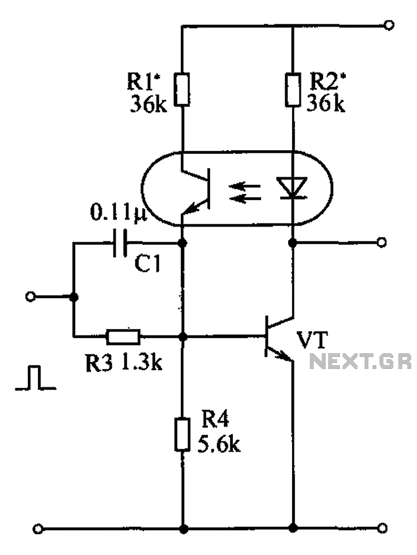
The bistable circuit and optocoupler transistor operate as illustrated in the accompanying figure. Initially, when the supply voltage is applied, the transistor VT is in the off state, resulting in a high output potential. Upon receiving a forward pulse...
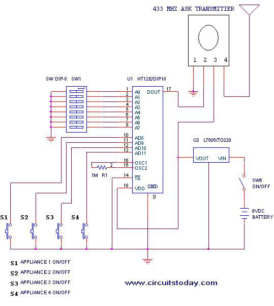
This project outlines a simple remote control system utilizing RF communication without the use of a microcontroller. The remote is designed for various home appliances such as televisions, fans, and lights, providing significant convenience by allowing operation from a...
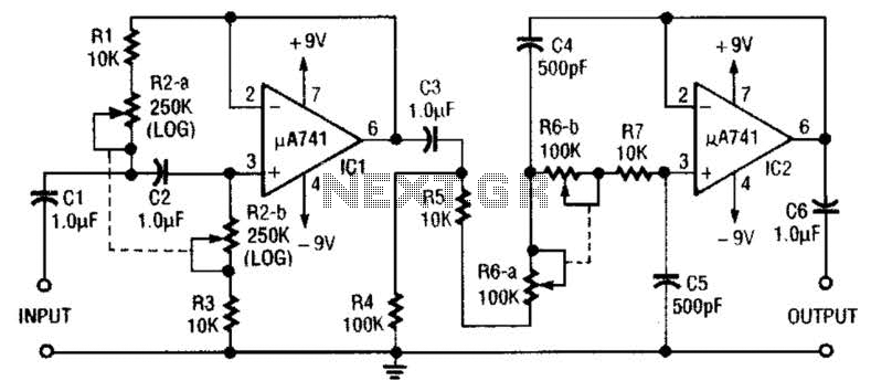
This circuit is a variable audio bandpass filter that features a low cutoff adjustable from approximately 25 Hz to 700 Hz and a high cutoff adjustable from 2.5 kHz to over 20 kHz. The roll-off is set at 12...
The Olimex P-40 development board will be utilized, though the circuit can also be constructed on a breadboard due to its simplicity. The schematic for the initial implementation of servo control is provided below. Servos, like any motors, can...
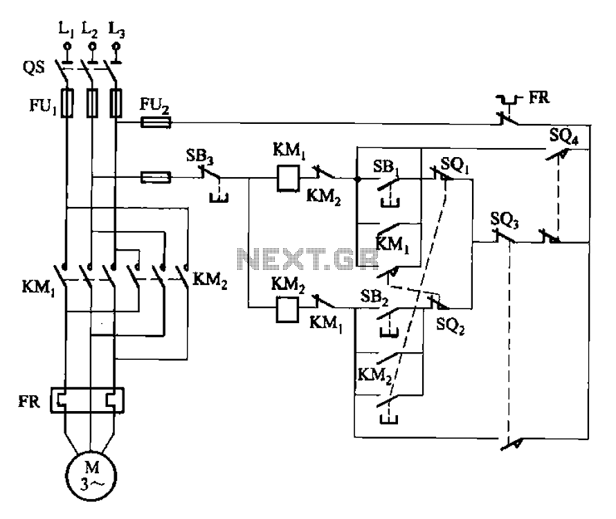
The circuit illustrated in Figure 3-132 represents an automatic round-trip plug braking circuit. To prevent or limit malfunctions of switch SQ1 and switch SQ2 that could lead to accidents, two additional protection limit switches, S03 and S04, have been...
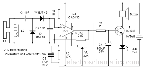
This circuit is designed to detect microwave sources, such as microwave ovens, satellite communication devices, and mobile phones. It provides audio-visual indications when microwaves in the gigahertz band are detected. Microwaves are a form of electromagnetic radiation with frequencies...
Warning: include(partials/cookie-banner.php): Failed to open stream: Permission denied in /var/www/html/nextgr/view-circuit.php on line 713
Warning: include(): Failed opening 'partials/cookie-banner.php' for inclusion (include_path='.:/usr/share/php') in /var/www/html/nextgr/view-circuit.php on line 713