
Eico667 troubleshooting

The Eico 667 tube tester schematic is a crucial tool for those involved in testing and restoring vacuum tubes. The design, while similar to the Eico 666, incorporates enhancements that may affect operational performance. The replacement of selenium diodes with 1N4007 diodes is a significant upgrade, as the latter provide better reliability and lower forward voltage drop, which is essential for maintaining the integrity of the tester's measurements.
The choice of filter capacitors is also vital; modern capacitors not only occupy less space but often have improved performance characteristics, such as higher ripple current ratings. The recommended values of 22uF/150VDC for C1 and 22uF/25VDC for C2 ensure that the power supply remains stable under varying loads, which is important for accurate testing results.
Calibration potentiometers R7 and R18 are critical components that directly influence the accuracy of the tester. The recommendation to replace these with high-quality potentiometers is based on the known reliability issues of the original controls. The use of a nylon shaft minimizes mechanical wear and potential failure points, ensuring longevity and consistent performance.
The calibration process itself is essential for achieving precise measurements. By setting the Line Adjust to yield 6.3VAC with a 6L6 tube, the technician can ensure that the tester operates correctly under load conditions. This step is crucial, as inadequate filament voltage can lead to inaccurate test results, particularly when testing other tube types that draw different amounts of current.
The design considerations for the switch in the transistor tester circuit highlight the importance of mechanical stability in electronic components. The presence of a tab to prevent rotation is a thoughtful design feature, but the lack of a corresponding hole in the panel can lead to complications. Proper installation techniques, including the use of spacers or additional nuts, can mitigate these issues and maintain reliable operation.
Overall, the Eico 667 tube tester schematic provides a comprehensive framework for restoring and maintaining this valuable piece of equipment, emphasizing the importance of quality components and careful calibration for optimal performance.Here is the schematic from the Eico 667 tube tester. It is very similar to the 666, except now there are a pair of extra levers, and a few test sockets are missing. But the meat and potatoes are identical. If you are planning to restore your 667 to peak operating condition, here are a few pointers. Replace the selenium diodes CR1 and CR2. I rivet in a small terminal strip, using the mounting hole from the `old` diodes. It is now easy enough to install 1N4007 diodes across the terminal strip. While you are at it, replace filter capacitors C1 and C2. Since modern-day capacitors are much smaller than their ancestors, I replace C1 with a 22uF/150VDC or possibly a 47uF/150VDC capacitor, while C2 is now a 22uF/25VDC capacitor. Typically I use whatever I happen to have on hand. Carefully check the calibration potentiometers R7 and R18. If you are having any difficulties calibrating your tester, change these potentiometers! Replace them with any quality 100K linear-taper potentiometer. I make sure I use a control with a nylon shaft, and avoid those with split and/or splined shafts. If necessary, I also cut a notch in the top of the shaft, to facilitate using a small screwdriver for any adjustments.
Eico used very poor quality controls here, and they are prone to failure. When doing the calibrating for the Line Adjust, I will set it so `High Noon` gives me a reading of 6. 3VAC with a 6L6 inserted in the socket! This may seem obvious, but I sometimes carefully calibrate the Line Adjust exactly as the manual describes, and I end up testing a 6L6 with barely 6VAC on the filaments.
I choose a 6L6 as opposed to a 6V6 because the filament draw is higher, and I want to be sure this procedure is done under a decent sized load! You can measure the filament voltage while testing say a 12AT7 or a 6SL7 after, and be sure your filament voltages are consistent, and correct!
Tweak the Line Adjust calibration as necessary. Finally, according to one Internet `expert`; The transistor tester circuit is comprised of the switch, the resistors, capacitor all are mounted on it. On some of the units the switch has a orientation tab. that is a tab that protrudes from the face of the switch and is meant to go into a hole in the mounting panel next to the shaft hole.
Its purpose is to keep the switch assembly from rotating when the selector knob is turned so that the position indicated on the panel will be the correct position on the switch. EICO did not have the extra hole in the face panel and, if no spacer washer are used between the rear of the panel and the face of the switch, when the shaft nut is tightened the tab hits the panel and if tightened enough warps the switch assembly.
Next thing you know is you get no contact on some of the terminals and no amount of adjusting the tension of the contactors will work for more than a few switchings. The warp causes the contact to be pushed up and away from the contact ring. I discovered the cause when I was trying to determine which contact was not making and pressed the ohm meter probe hard against the terminal and I get contact, relieve the pressure and no contact, Looking at the rear of the switch, it affects the terminals on the front side of the switch which are hard to see no less adjust.
If you have a switch with the tab don`t tighten the switch too tight or you will warp it. I cut off the tab (closing the barn door after the cows are gone) but you can also cure problem by using a second nut on the shaft thread adjusted so tab will not hit mounting surface or add a few washers (not lock washers as they collapse a little when you tighten them [this is what happened to me]) which will have the same effect. The prior owner used the lock washers and either he or I did the warping! Hope this helps someone, those switch are hard to find in that configuration, five pole /five throw. Makes perfect sense to me. Although I leave my switch in the `Tube T 🔗 External reference
Related Circuits
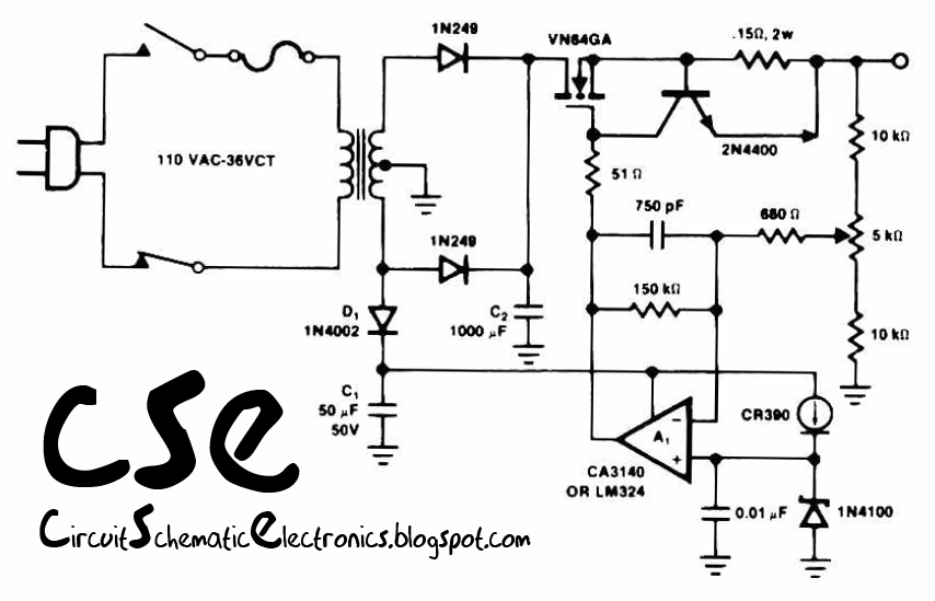
This circuit utilizes the operational amplifier IC LM324 to drive the VN64GA with an error signal and to regulate the output voltage. The output voltage generated is pulsating DC, which is suitable for battery charging applications. Additionally, this circuit...
Connect 22k fixed resistors across each transistor base and ground, then connect the leads of a 50K dual potentiometer across these resistors to imitate variations similar to a 10k potentiometer. Remove the 10K resistors connected to the base of...
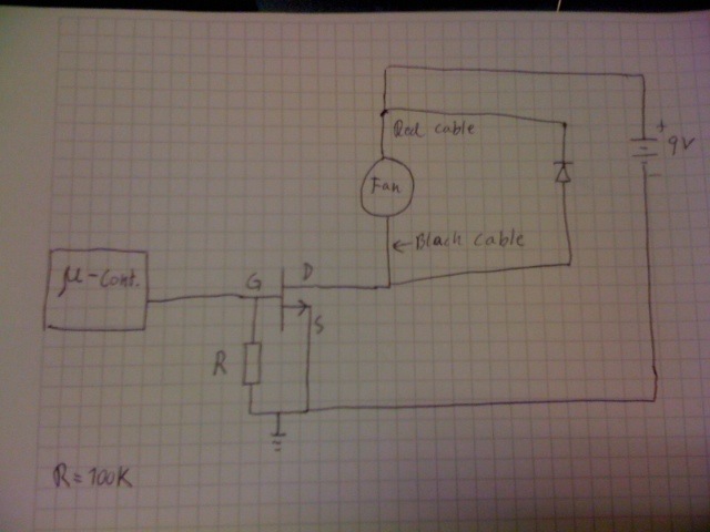
Control a fan using an LM34 temperature sensor and a computer fan with model number ASB0912L. A 2N7000 MOSFET transistor is utilized as a switch. The fan is intended to operate at a 35% duty cycle when the temperature...
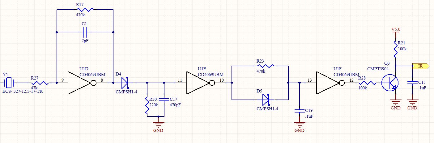
This is a follow-up to an earlier post regarding a specific circuit schematic. The circuit is designed to operate at a supply voltage of 5V, and testing has confirmed that the original device functions correctly at this voltage. A...
Even though the power was off, there was AC present at the handle plug, and a short circuit occurred. Upon disassembly, a blown transistor was discovered. An attempt was made to fix the issue, but after one month and...
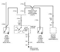
The following circuit illustrates the wiring diagram and electrical circuit troubleshooting for the 1997 Chevrolet Blazer. Features include a 4.3-liter Vortec V-6 engine, an AM-FM stereo radio with CD player, rear-wheel drive managed by a four-speed automatic transmission, air...