
Fan control troubleshooting Microcontroller Programming

The circuit design involves a temperature control system that regulates the operation of a fan based on temperature readings from an LM34 temperature sensor. The LM34 sensor provides an analog output that is proportional to the temperature in Fahrenheit. The microcontroller used in this design is the ATmega168, which processes the sensor's output and controls the fan's operation through a PWM signal.
The fan, identified as ASB0912L, is a standard computer fan that operates efficiently with PWM control. The 2N7000 MOSFET serves as a switch, allowing the microcontroller to turn the fan on and off based on the PWM signal. When the temperature exceeds the threshold of 77°F, the microcontroller sets the PWM output to a value that corresponds to a 35% duty cycle, providing sufficient power to the fan. Conversely, if the temperature is at or below 77°F, the PWM output is set to 0%, effectively turning off the fan.
The program begins by defining essential constants and includes necessary libraries for handling I/O operations, analog-to-digital conversion, and PWM generation. The `pwm_init()` function configures the timer for Fast PWM mode, allowing for smooth control of the fan speed. The `adc_init()` function initializes the analog-to-digital converter, setting it up to read the output from the LM34 sensor.
The `adc_read()` function retrieves the current temperature reading from the ADC, and the `sampleToFahrenheit()` function converts the ADC value into a temperature in Fahrenheit. The main loop of the program continuously checks the temperature, adjusts the PWM signal accordingly, and updates the fan's operation status.
This control system is designed to maintain a comfortable environment by automatically adjusting the fan speed based on real-time temperature readings, thereby optimizing energy consumption and improving comfort. Proper attention should be given to the code logic to ensure accurate temperature readings and PWM signal adjustments to avoid the issue of the fan running continuously.Control a fan using an LM34 temp sensor and a computer fan with model number : ASB0912L. I used a 2N7000 mosfet transistor as a switch. I want my fan to run at 35% duty cyle when the temperature is above 77 fahrenheit and to run at 0% duty cycle when temperature is equal to or less then 77 fahrenheit. I tried using the code below but the fan keeps running all the time. // fan_controller. c // for NerdKits with ATmega168 #define F_CPU 14745600 #define PWM_fanspeed_2 12915 //For 7ms high time = 35% duty cycle #define PWM_fanspeed_START 0 #include
TCCR1B = (1<
🔗 External reference
Related Circuits
The figure illustrates a schematic for an oscillator amplitude-control servo system. The circuit establishes a closed-loop system that provides a fixed and adjustable peak-to-peak amplitude AC signal centered around 0 V. A 1 kHz sine wave, designated as AC_INPUT,...
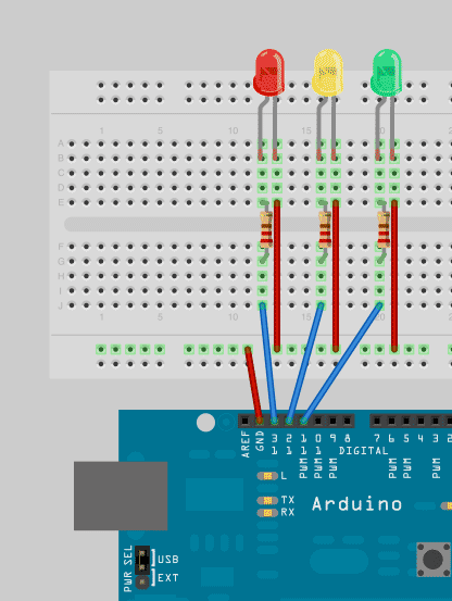
To enhance Arduino programming skills, developing a traffic light controller serves as an excellent practice project. The traffic light controller project involves designing a circuit that simulates the operation of a traffic light system, typically consisting of red, yellow, and...

Conducting pipe rechargeable long delay control circuit. An adjustment potentiometer RP can delay up to several tens of seconds. The conducting pipe rechargeable long delay control circuit is designed to manage the timing of electrical signals, allowing for a delay...
The function of the TRIS registers, specifically TRISA and TRISB, governs the data transfer direction for each pin on Port A and Port B, respectively. A mnemonic to remember the TRIS register settings is to associate the numbers 0...
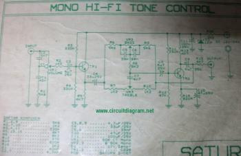
The following diagram illustrates the circuit of a 20-band stereo graphic equalizer, which is designed to control audio signals within specific frequency ranges. This circuit should be connected prior to the amplifier circuit. For optimal performance, it is recommended...
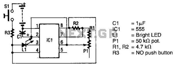
The circuit utilizes a 555 timer integrated circuit (IC) to drive an ultrabright LED. The output generated is a pulsing red light that can be focused using lenses. An ultrabright Stanley LED, which produces an output of 300 millicandela,...