
stereo fm transmitter using bh1417

The stereo FM transmitter circuit leverages the BH1417 PLL Stereo Transmitter IC, which is integral for achieving high-quality audio transmission. The architecture of this circuit is designed to manage audio signals separately for the left and right channels, ensuring a faithful reproduction of stereo sound. This separation is critical for providing a rich listening experience, as it maintains the integrity of the audio signals.
To enhance performance, the circuit includes an antenatal care section that significantly improves the signal-to-noise ratio. This feature is essential for minimizing interference and ensuring that the transmitted audio remains clear and undistorted. The control circuits are responsible for maintaining the accuracy of the transmission frequency, effectively blocking any unwanted frequencies that may disrupt the signal.
The multiplex circuit plays a vital role in the operation of the transmitter by generating the necessary audio signals for stereo transmission. It combines the left and right audio channels into a single output while preserving the unique characteristics of each channel. This process is crucial for delivering high-fidelity audio to the receiver.
The frequency adjustment capability of the transmitter is facilitated by a 4-switch DIP switch, allowing users to select from 14 different frequencies with a spacing of 0.2 MHz. This flexibility is particularly useful in environments where multiple transmitters may be operating, as it helps to avoid interference between channels.
Powering the BH1417 IC requires a DC voltage between 4 to 6 V, which is manageable for most battery-operated applications. The output power of approximately 20 mW is sufficient for short-range transmission, making it ideal for personal use or small-scale broadcasting. The low current consumption of 20 mA at full power output contributes to the efficiency of the circuit, allowing for extended operation without frequent battery replacements.
Overall, the design of this stereo FM transmitter circuit is characterized by its simplicity and effectiveness, making it a valuable tool for audio enthusiasts and hobbyists seeking to explore FM transmission technology. The precision of the PLL circuit ensures that the transmitter operates reliably over time, with minimal frequency drift, thus maintaining a consistent listening experience.The circuit shown here is a simple stereo FM transmitter that can transmit signals of high quality with a range of 70 feet. The circuit is based on BH1417 PLL Stereo Transmitter IC semiconductor Rhom. The IC has separate sections of audio processing for the left and right, the circuit of antenatal care to improve the signal to noise ratio, the con
trol circuits of glass blocking the precise frequency, multiplex circuit for making the sum (left over right) and the difference (to the left without right) {See this article for a better understanding of the stereo decoder circuit} etc. Another important feature of this circuit is that the transmission frequency can be set using a channel 4-switch DIP.
The IC can be powered by a figure between 4 to 6 V DC and has an output of about 20 mW. At full power output of the circuit consumes only 20 mA and has a channel spacing of 14 possible frequencies 40dB. There transmission default, from 88. 7MHz and increasing in steps of 0. 2MHz can be selected via DIP switch. The PLL circuit of the IC is so precise that there is virtually no frequency drift 🔗 External reference
Related Circuits
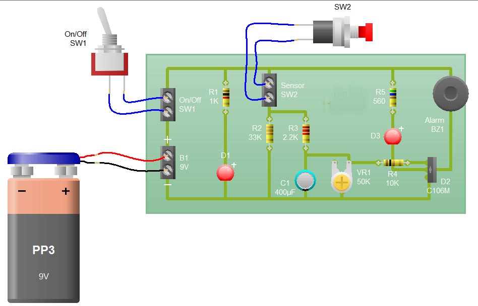
When the sensor switch SW2 is pressed, the LED D3 and the alarm are activated for a certain duration. The timing of the circuit is determined by the resistor R3 and capacitor C1. Additional details regarding the RC circuit...
Below are a couple circuits you can use to produce a 32.768 KHz square wave from a common watch crystal. The output can be fed to a 15 stage binary counter to obtain a 1 second square wave. The...
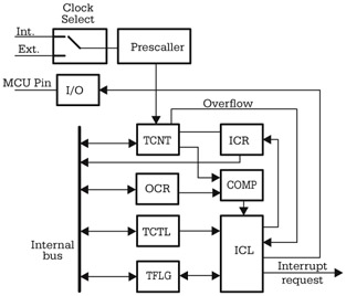
Although there are significant variations between different implementations of the general-purpose timer in various microcontrollers, many similarities exist in the principles of operation and the structure of the timer subsystem. The central element of the timer subsystem is a...
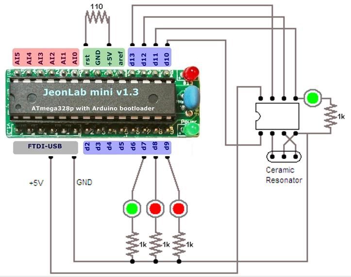
For relatively small projects with fewer pins than the ATmega328, the ATtiny series, specifically the ATtiny45 or ATtiny85, is a good choice due to its compact physical size. The ATtiny series microcontrollers, particularly the ATtiny45 and ATtiny85, are designed for...
The AVR Basic Infrared Transmitter is a companion project to the Basic Infrared Receiver. This project is termed "basic" because it can be constructed using only 10 discrete components along with a standard AVR microcontroller. Together, these two projects...
This circuit is a long-range infrared transmitter designed to enhance the power of infrared transmitters. Most infrared remotes operate effectively within a range of approximately 5 meters. The complexity of the circuit increases when designing for extended range capabilities. The...