
Electret mic pre amp

The electret microphone preamplifier circuit is designed to amplify the weak audio signals produced by electret microphones, which are commonly used in various applications due to their compact size and decent performance. The core component of this circuit is an operational amplifier (op-amp), which is configured in a non-inverting amplifier configuration to achieve the desired gain.
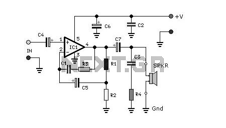
In the schematic, the microphone is connected to the non-inverting input of the op-amp. The op-amp's gain is determined by the feedback network formed by resistors R3 and R4. Resistor R3 is connected between the output of the op-amp and the inverting input, while R4 connects the inverting input to ground. The gain (Av) of the op-amp can be calculated using the formula:
Av = 1 + (R3/R4)
By selecting appropriate values for R3 and R4, the gain can be set to a fixed level, typically around 30 dB for standard applications. However, to provide flexibility in gain adjustment, R4 can be substituted with a potentiometer. The potentiometer allows the user to vary the resistance, thus changing the gain dynamically.
In the proposed configuration, replacing R4 with a 470K potentiometer in series with a 10K resistor allows for a gain range from 10 dB to 45 dB. This is particularly useful in applications where different levels of amplification may be required, such as in audio processing or recording systems.
The circuit may also include additional components such as decoupling capacitors to filter out noise and stabilize the power supply, ensuring that the op-amp operates effectively. Proper layout and grounding techniques should be employed in the PCB design to minimize interference and maintain signal integrity.Electret mic pre amp schematic. The op amp provides an amplification of about 30 dB (which is sufficient for the relatively high output level of an electret microphone), this gain depends on the value of resistors R3 and R4. If you want to be able to vary the gain, simply replace the resistor R4 to 120K a 470K potentiometer in series with a resist
ance of 10K. The overall gain in this way can vary from 10 to 45 dB. 🔗 External reference
Related Circuits
The circuit is designed to deliver approximately 10% distortion on a 4 Ohm to 8 Ohm loudspeaker. The LM4756 amplifier can output 7W of power. Utilizing four pairs of 2SC5200 and 2SA1943 transistors, this configuration can generate around 500W....
For several years, a rear fog lamp has been mandatory for trailers and caravans to enhance visibility in foggy conditions. When the fog lamp is activated, the fog lamp of the towing vehicle must be turned off to prevent...
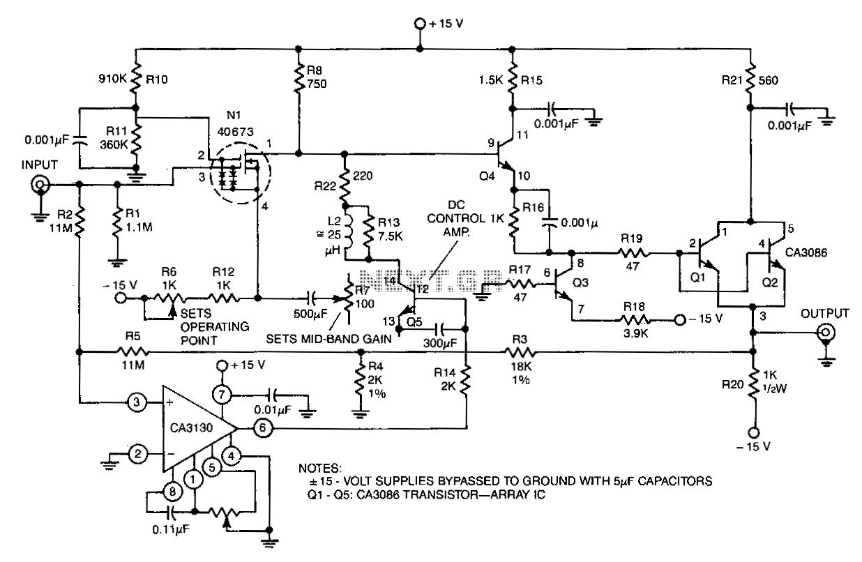
The circuit features an input resistance of 1 MΩ, a bandwidth extending from DC to approximately 35 MHz, and a gain of 10 times. Low-frequency gain is achieved using a CA3130 BiMOS operational amplifier configured as a single-supply amplifier....
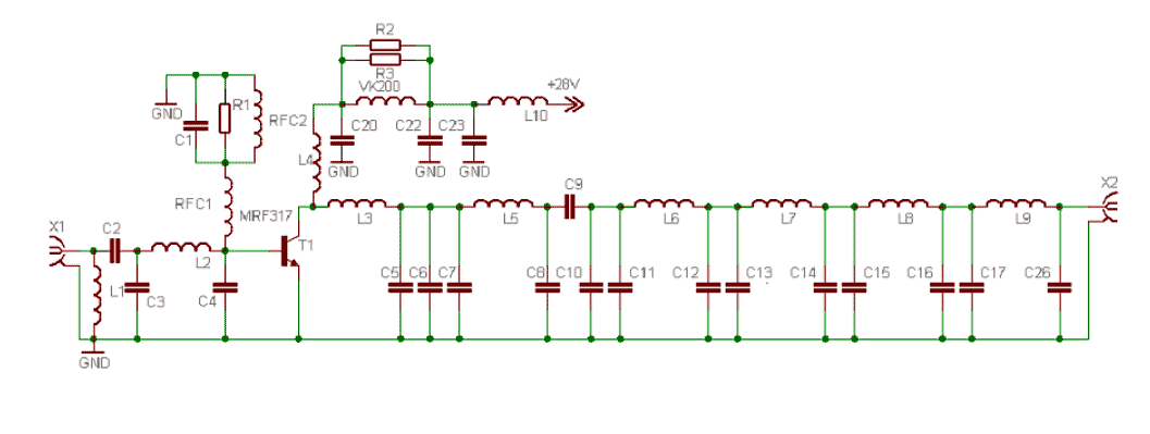
This power amplifier is equipped with a bipolar transistor, the famous MRF317. As in many FM amplifier applications, the power transistor is in a C class bias. All the impedance networks (input & output) have been determined by using...
The circuit allows a precision regulated drive current to be set to drive an LED, and in response to a TTL level signal, the LED is switched on and off with rise and fall times of less than 500...
This circuit enables a remote microprocessor to be reset by a controlling host via a remote RS-232 or similar protocol serial line. Utilizing a program loader on the remote host, a program can be downloaded and executed. This functionality...