
Fundamentals of Electrical Engineering and Simple combination lock
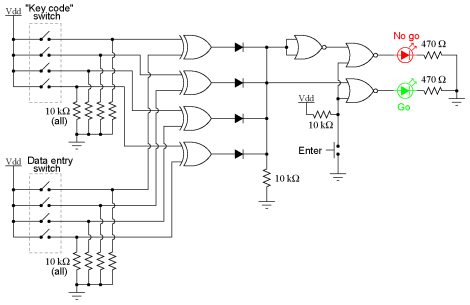
The circuit design incorporates an 8-position DIP switch configured to facilitate binary code entry, utilizing the leftmost four switches for user input and the rightmost four switches to store the "key" code. This arrangement allows for a clear visual distinction between the code entry and storage functions. The XOR gates are pivotal in comparing the two sets of binary inputs, providing outputs that determine the state of the LEDs. The integration of diodes in the output stage ensures that the circuit can handle multiple signal inputs without interference, effectively allowing for a single "high" output to trigger the NOR gate. The NOR gate's role in the circuit is crucial; it acts as a control mechanism, ensuring that the LEDs only respond to the input from the "Enter" pushbutton, thereby preventing false activation. This design emphasizes the importance of logical circuitry in creating functional and secure electronic systems.This experiment may be built using only one 8-position DIP switch, but the concept is easier to understand if two switch assemblies are used. The idea is, one switch acts to hold the correct code for unlocking the lock, while the other switch serves as a data entry point for the person trying to open the lock.
In real life, of course, the switch a ssembly with the "key" code set on it must be hidden from the sight of the person opening the lock, which means it must be physically located elsewhere from where the data entry switch assembly is. This requires two switch assemblies. However, if you understand this concept clearly, you may build a working circuit with only one 8-position switch, using the left four switches for data entry and the right four switches to hold the "key" code.
This circuit illustrates the use of XOR (Exclusive-OR) gates as bit comparators. Four of these XOR gates compare the respective bits of two 4-bit binary numbers, each number "entered" into the circuit via a set of switches. If the two numbers match, bit for bit, the green "Go" LED will light up when the "Enter" pushbutton switch is pressed.
If the two numbers do not exactly match, the red "No go" LED will light up when the "Enter" pushbutton is pressed. Because four bits provides a mere sixteen possible combinations, this lock circuit is not very sophisticated.
If it were used in a real application such as a home security system, the "No go" output would have to be connected to some kind of siren or other alarming device, so that the entry of an incorrect code would deter an unauthorized person from attempting another code entry. Otherwise, it would not take much time to try all combinations (0000 through 1111) until the correct one was found!
In this experiment, I do not describe how to work this circuit into a real security system or lock mechanism, but only how to make it recognize a pre-entered code. The "key" code that must be matched at the data entry switch array should be hidden from view, of course.
If this were part of a real security system, the data entry switch assembly would be located outside the door, and the key code switch assembly behind the door with the rest of the circuitry. In this experiment, you will likely locate the two switch assemblies on two different breadboards, but it is entirely possible to build the circuit using just a single (8-position) DIP switch assembly.
Again, the purpose of the experiment is not to make a real security system, but merely to introduce you to the principle of XOR gate code comparison. It is the nature of an XOR gate to output a "high" (1) signal if the input signals are not the same logic state.
The four XOR gates` output terminals are connected through a diode network which functions as a four-input OR gate: if any of the four XOR gates outputs a "high" signal - indicating that the entered code and the key code are not identical - then a "high" signal will be passed on to the NOR gate logic. If the two 4-bit codes are identical, then none of the XOR gate outputs will be "high, " and the pull-down resistor connected to the common sides of the diodes will provide a "low" signal state to the NOR logic.
The NOR gate logic performs a simple task: prevent either of the LEDs from turning on if the "Enter" pushbutton is not pressed. Only when this pushbutton is pressed can either of the LEDs energize. If the Enter switch is pressed and the XOR outputs are all "low, " the "Go" LED will light up, indicating that the correct code has been entered.
If the Enter switch is pressed and any of the XOR outputs are "high, " the "No go" LED will light up, indicating that an incorrect code has been entered. Again, if this were a real security system, it would be wise to have the "No go" output do something that deters an unauthorized person from discovering the correct code by trial-and-error.
In other words, there should be some sort of penalty f 🔗 External reference
Related Circuits

One of the simplest methods of metal detection is through a beat frequency oscillator. The circuit consists of two balanced oscillators: one provides a reference signal, while the other acts as the detector element. The frequency of the reference...

A low-cost, simple radio circuit schematic using an operational amplifier. This radio circuit diagram consists of a sensitive audio amplifier that receives strong signals. The presented radio circuit schematic utilizes an operational amplifier (op-amp) to create a cost-effective and straightforward...
U2 is a decade counter/divider, U1 is used as a switch debouncer. For a self-generating system, connect a resistor between pins 2 and 3 of U1, value that should be between 10 KOhm and several, depending on desired frequency....

The diagram illustrates a block diagram for an agenda alarm and agenda thermometer system. It includes one temperature sensor, a real-time clock (RTC), a microcontroller (PIC), an EEPROM, a 7-segment display, and a keyboard. The EEPROM is utilized to...

Originally, the tank cost around Php 400 but was later sold for approximately a hundred pesos less. Recognizing a great deal, the decision was made to purchase the toy. Opening the toy proved to be somewhat challenging. The track...

The circuit for the RS232 serial interface exhibits mild complexity. The primary components of the circuit include the 18F4520 microcontroller, MAX233A level shifter, and a DB-9 connector. This circuit utilizes a basic +5V power regulator to supply the digital...