
Electronic Keypad
The circuit described operates as a sequential key code entry system, utilizing a series of logic gates to validate the input sequence. The primary component is the CMOS 4081 integrated circuit, which contains four dual-input AND gates. Each gate serves as a stage in the sequence, where the output of one gate is connected to the input of the next, thus creating a chain of dependencies.
The process begins with four keys designated as A, B, C, and D. Each key must be pressed in the correct order for the alarm to deactivate. When a key is pressed, it provides a HIGH signal to the corresponding input of the first AND gate. The output of this gate will only be HIGH if both of its inputs are HIGH, which means that the previous key in the sequence must have been pressed correctly.
If an incorrect key is pressed, the first gate's output will drop to LOW, effectively disabling the entire sequence. This design relies on the principle of cascading logic gates, where each gate must be satisfied for the subsequent gate to function correctly.
Pin 1 of the first gate is held HIGH by a resistor R4, ensuring that the sequence can begin. Resistor R1 and diode D1 are used in conjunction with the key connected to input E. When this key is pressed, it allows current to flow through R1, turning on transistor Q5. This transistor acts as a switch that energizes a relay, which can be used to control the alarm system.
The relay's activation signifies that the correct sequence of keys has been entered, allowing the alarm to switch off. The design emphasizes the importance of correct timing and order in the key presses, making it a secure method for deactivating the alarm while preventing unauthorized access through incorrect entries.The alarm will switch off when the 4 keys connected to "A,B,C,D" are pushed in the right order.The circuit works because each gate `Stands` upon its predecessor.If any key other than the correct key is pushed, then gate 1 is knocked out of the stack, and the code entry fails. Pin 1 is held high by R4. The IC is a quad 2 input "AND" gate, a CMOS 4081. These gates only produce a HIGH output, when BOTH the inputs are HIGH. When the key wired to `E` is pressed, current through R1 and D1 switchs Q5 on.The relay energises; and Q5 is ' 🔗 External reference
Related Circuits
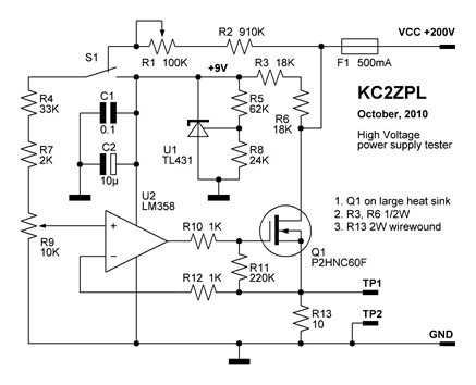
Now that these power supplies are available, it would be beneficial to evaluate their performance. Traditionally, an adjustable load (a robust resistor) is connected to the output to measure both output voltage and current at various points. This allows...
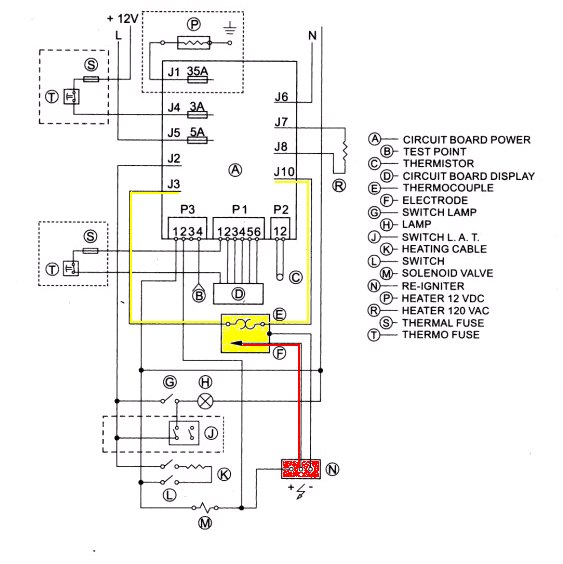
With the exception of pilot-type water heaters and some smaller LP/Electric refrigerators, modern LP appliances in RVs are controlled by electronics. Modern LP (liquefied petroleum) appliances utilized in recreational vehicles (RVs) have largely transitioned to electronic control systems, enhancing their...
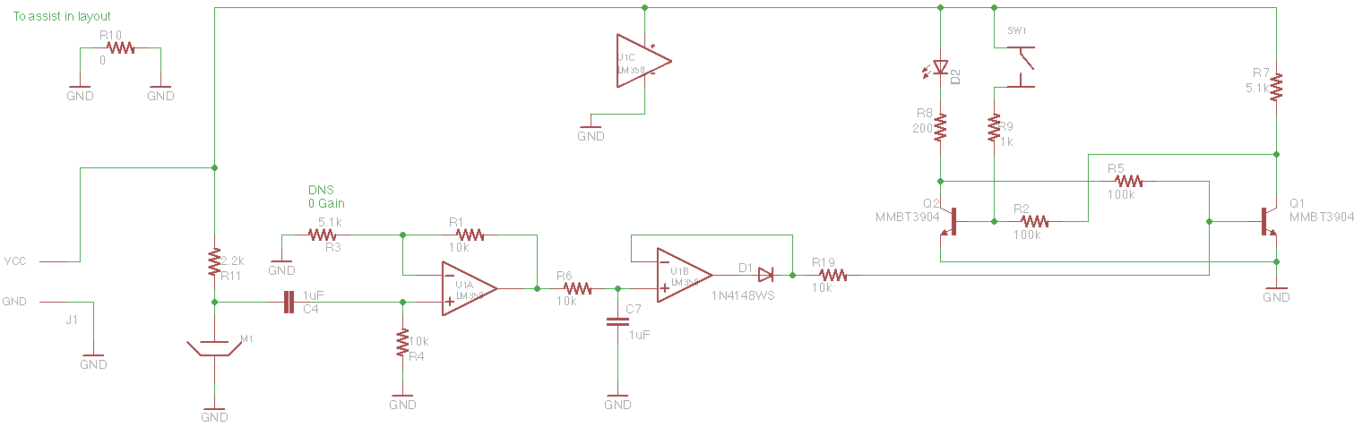
The concept involves mounting a microphone on a stick with an LED and designing a circuit that responds to loud noises detected by the microphone input (such as blowing) to turn off the LED. The schematic is straightforward, powered...
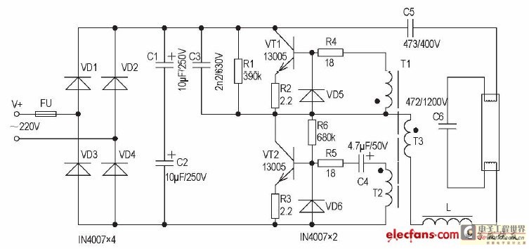
The inductive ballast has several drawbacks, including larger size and weight, high power consumption, and noise generation. In contrast, the electronic ballast features a low-voltage starter, is non-stroboscopic, operates silently, is energy-efficient, and provides immediate lighting without flickering. This...
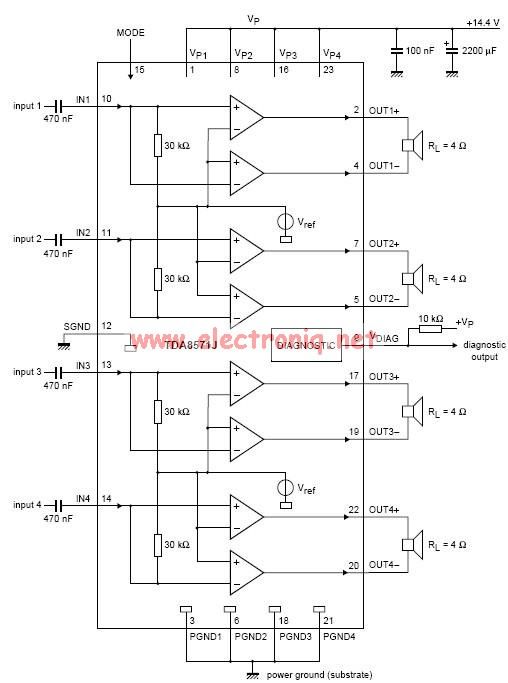
This electronic circuit diagram represents an audio power amplifier utilizing the TDA8571J integrated circuit. It is a class-B output amplifier configured in a BTL (Bridge-Tied Load) arrangement, featuring four amplifiers, each with a gain of 34 dB. The main...
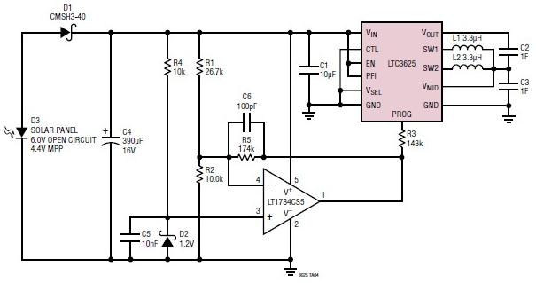
A simple supercapacitor charger electronic project can be designed using the LTC3625 integrated circuit (IC) from Linear Technology. This circuit is capable of charging two supercapacitors in series to a fixed output voltage of either 4.8V/5.3V or 4V/4.5V, which...