
electronic canary
The modified Hartley oscillator is a type of LC oscillator that uses an inductor-capacitor (LC) circuit to generate a continuous wave signal. This oscillator configuration is particularly notable for its simplicity and effectiveness in producing audio frequencies, making it suitable for applications such as sound generation in doorbells or novelty devices.
In a typical Hartley oscillator circuit, two inductors (L1 and L2) and one capacitor (C) are used. The inductors are connected in series, and the output is taken from the junction of the inductors. The feedback path is crucial for sustaining oscillations, which is often provided by a transistor or an operational amplifier. The values of the inductors and capacitor determine the oscillation frequency, which can be adjusted by varying these components.
For the doorbell application, the output signal can be connected to a small speaker or piezo buzzer to produce a chirpy sound when the circuit is activated. The oscillator can be triggered by a push button switch, providing an engaging sound to greet visitors. Additionally, the circuit may include a power supply section, typically consisting of a battery or a low-voltage power adapter, ensuring the oscillator operates efficiently.
The design can be further enhanced by incorporating a variable resistor (potentiometer) to adjust the frequency of the oscillations, allowing customization of the sound produced. This feature can make the doorbell sound unique and more appealing to users. Overall, the modified Hartley oscillator offers a versatile solution for generating audio signals in various applications, making it a valuable component in electronic design.Feeling chirpy? Attract new friends with this modified hartley oscillator. You could also use it as a replacement doorbell.. 🔗 External reference
Related Circuits
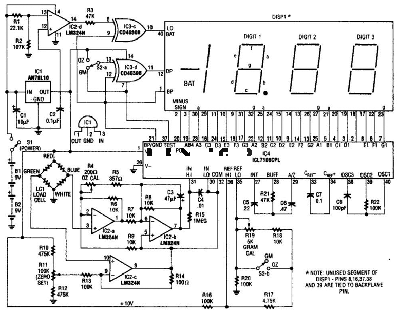
An electronic scale utilizes a pressure transducer (load cell) along with an analog-to-digital (A/D) converter to operate a digital display. The scale's range is determined by the specifications of the load cell, and the display is calibrated in suitable...
This circuit is very basic to build. To open a the lock which is connected to the K1 Load you must press each momentary switch in the correct sequence. The sequence used in this circuit is S1, S2, S3,...
This circuit is a modification of the Hartley oscillator, incorporating several additional components. It utilizes a small audio transformer. The modified Hartley oscillator circuit enhances the traditional design by integrating extra components that can improve performance characteristics such as stability,...

This design outlines a door alarm circuit that utilizes an electronic system. It features a synthesized sound chip from Holtek, specifically the HT-2811, which reproduces the sound of a "ding-dong" chiming doorbell. The circuit also incorporates a CMOS 4026...
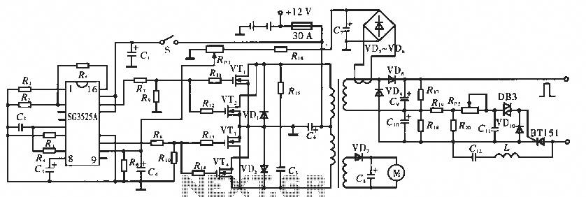
The circuit utilizes the SC3525A, a PWM silicon chip from US General Semiconductor. It features an error amplifier with an inverting input at pin 1. Pin 2 serves as the non-inverting input for the error amplifier. Pins 5 and...
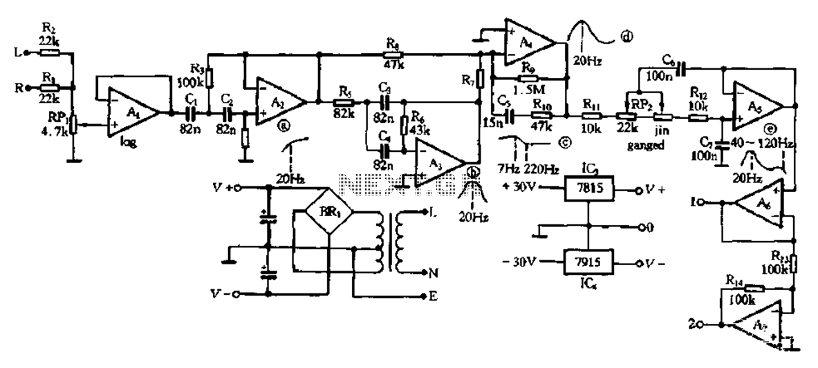
This electronic bass equalizer circuit utilizes two quad operational amplifiers, specifically the TL084 high-speed operational amplifier. The circuit includes left and right channels that are mixed through resistors R1 and R2, and features a total bass level adjustment potentiometer...