
Electronic Canary

The circuit diagram represents a reverse-engineered electronic bird sound generator, commonly found in decorative items such as Christmas ornaments. The primary power source for the first variant is a 9V battery, which provides sufficient voltage to drive the audio output at a higher volume, suitable for larger ornaments or applications where sound projection is essential.
The circuit utilizes an audio transformer labeled L1, which is primarily responsible for amplifying the audio signal generated by the oscillator circuit. The unused secondary winding of the transformer indicates that the design may have been simplified or that additional features were omitted in this variant. The oscillator typically consists of a combination of resistors, capacitors, and a transistor or integrated circuit, which together create a square wave signal that simulates bird sounds.
In the second variant operating on 3VDC, powered by two AA cells, the design is streamlined to reduce component count. This lower voltage operation results in a quieter output, making it more suitable for smaller ornaments or applications where a subtle sound is desired. The use of fewer components not only simplifies the assembly process but also reduces manufacturing costs.
Both circuits likely include a sound-producing element, such as a piezoelectric speaker or a small speaker, which converts the electrical signals into audible sound. The design variations among the different models may include changes in the oscillator frequency, the type of speaker used, or additional components to enhance sound quality or modify the sound characteristics.
Overall, these electronic bird circuits exemplify compact design principles in consumer electronics, demonstrating how sound generation can be achieved efficiently while maintaining a focus on user experience and product aesthetics.Reverse engineered circuit diagram of a commercial Electronic Bird. This one was built into a plastic christmas ornament and runs off a 9V battery. Note that L1 is actually just an audio transformer with an unused secondary winding. Here is another commercial circuit of the same type as shown above, but this one operates on 3VDC supplied by two AA cells. It is therefore able to use fewer parts but is not as loud. These ones run off a single AA cell and there are three slightly differ 🔗 External reference
Related Circuits

Cats are natural predators of rats, and the use of electronic devices to simulate meowing sounds as a repellent is an effective method. These electronic devices can produce meowing sounds at various frequencies and intervals, making them suitable for...
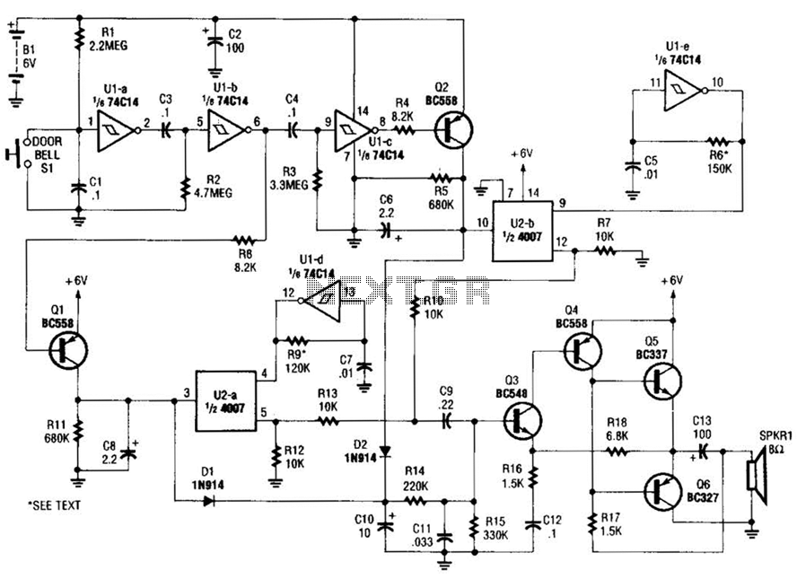
When the doorbell switch is pressed, two monostable stages are sequentially activated, applying bias to a pair of voltage-controlled resistor stages. These stages modulate the outputs from a pair of tone generators. The resulting signals are then fed to...

This USB to Serial RS232 adapter is highly beneficial in scenarios where a device with RS232 needs to be connected to a computer lacking an RS232 port but equipped with a USB port. Utilizing the FT232BM chip produced by...

The circuit consists of two twin-T oscillators configured to operate just below the oscillation threshold. To initiate oscillation, the circuit can be activated by touching the Touch Pad. The circuit utilizes twin-T oscillator configurations, which are known for their ability...

This circuit generates the sound of two canaries singing in a cage. Two LM324 quad amplifiers constitute seven oscillators. One oscillator serves as an on/off control, while the remaining six produce the sounds of two canaries. A 9-V supply...
The fishing circuit, as illustrated in figure 11-6, comprises a timing circuit and an audio circuit. The components 555, RP1, and C1 form the single-shot circuit, with the defined time calculated as td = 1.1RP1C1. The maximum defined time...