
ELECTRONIC DICE
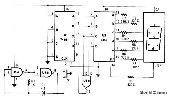
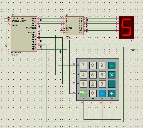
The circuit described involves a simple counting mechanism that utilizes a switch (S1), a counter (U2), and an oscillator (U1A/U1B). When the switch S1 is engaged, it triggers the oscillator, which generates a clock signal to drive the counter U2. The counter is capable of counting from 0 to 6, and the current count is visually represented on a display unit labeled DISP1.
The oscillator, comprised of operational amplifiers U1A and U1B, provides a square wave signal that determines the speed at which the counter increments. The frequency of this oscillation is influenced by the values of resistor R1 and capacitor C1, which form an RC timing circuit. The selection of R1 and C1 is critical; they must be chosen to produce a count rate that is fast enough to appear random to the user. This randomness is essential for applications such as gaming or random number generation, where predictable outputs are undesirable.
In practical terms, the values of R1 and C1 can be calculated using the formula for the time period of an RC circuit, which is T = R1 * C1. The frequency (f) of the oscillation can then be derived from the time period (f = 1/T). It is advisable to experiment with different resistor and capacitor values to achieve the desired count rate and ensure that the display updates rapidly enough to give the appearance of randomness.
The output from the counter U2 is connected to the display DISP1, which could be a seven-segment display or an LCD, depending on the design requirements. The display circuitry should be designed to handle the output format from U2 correctly, ensuring that the count is visually represented accurately and clearly.
In summary, this circuit effectively combines a switch, oscillator, counter, and display to create a simple yet functional counting mechanism with a focus on producing a random count output. Proper selection of components is essential to achieve the desired operational characteristics.When S1 is pressed, counter U2 is driven by oscillator U1A/U1B and the count (0 through 6) is read on DISP1. R1 and C1 determine the count rate, which should be fast enough to ensure a "random" count. 🔗 External reference
Related Circuits
This document provides a guide on understanding a simple computer system and its operation. It will examine the BASIC programming language and its statements, enabling communication with external circuitry. The document will also explore how to interface electronic circuits...
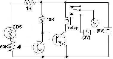
This circuit was submitted by Adam from Canada who is still at school. I have provided the text. The two transistors are used as a direct coupled switch, Adam used 2SC711 but any general purpose transistor will do e.g....
This circuit generates a ringing sound akin to that produced by modern telephones. It comprises three nearly identical oscillators arranged in a sequence, each responsible for generating a square wave signal. The frequency of each oscillator is determined by...
Figure 1-1 illustrates a general-purpose timer capable of timing intervals ranging from 5 minutes to 18 hours. The timing cycle can be adjusted to span from 5 minutes to 20 hours, with a maximum control time of 18 hours....
A keyboard key functions by establishing an electrical contact between the surface of the keyboard and the underlying circuit when the keytop area is pressed. This mechanism was utilized by some home computers in the early 1980s and has...
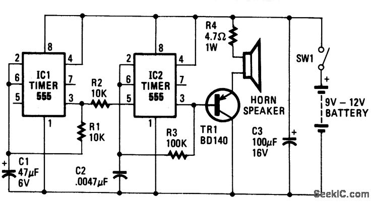
The oscillator based on IC2 generates sound, with its output linked to the base of TR1, which amplifies the signal to drive the speaker. Resistor R4 is included to limit the current through TR1 to a safe level. The...