
HEE HAW ELECTRONIC SIREN
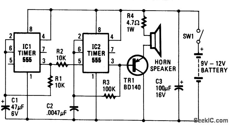
The circuit employs two integrated circuits (IC1 and IC2) to create a sound-generating oscillator system. IC2 serves as the primary sound generator, producing a frequency that is modulated by external components, specifically resistor R3 and capacitor C2. This configuration allows for fine-tuning of the oscillation frequency, which is crucial for achieving the desired sound output.
The output from IC2 is fed into the base of transistor TR1, which acts as an amplifier. The purpose of TR1 is to boost the signal strength sufficiently to drive a connected speaker, ensuring that the sound produced is audible. Resistor R4 plays a critical role in protecting TR1 from excessive current, thereby ensuring reliable operation and preventing damage to the transistor.
Moreover, the frequency of oscillation at IC2 can be dynamically altered by adjusting the voltage at pin 5. This feature introduces versatility into the design, allowing for variations in sound output based on the input voltage. When a varying voltage is applied, it causes the internal circuitry of IC2 to reset at different intervals, resulting in changes to the oscillation frequency.
IC1 operates as a secondary oscillator, generating a much slower frequency of approximately 1 Hz. This slower oscillation is utilized to trigger IC2, as the high voltage at pin 3 of IC1 is connected to pin 5 of IC2. Each time IC1 completes a cycle, it sends a pulse to IC2, prompting it to change its output frequency. This interaction between the two ICs creates the characteristic "hee-haw" sound of the siren, effectively combining the fast oscillation of IC2 with the slower triggering of IC1 to produce a unique auditory effect.
In summary, this circuit design effectively utilizes the properties of oscillators and transistors to create a sound-generating system with adjustable frequency characteristics, ensuring both functionality and protection for its components.The oscillator based on IC2 is responsible for producing the sound. Its output is connected to the base of TR1, which amplifies it to drive the speaker. Resistor R4 is included in the circuit to limit the current through TR1 to a safe and reasonable level. The oscillation frequency of IC2 is partially dependent on the values of R3 and C2. Another factor that governs the frequency of oscillation is the magnitude of voltage fed to pin 5 of IC2. If a voltage of varying magnitude is fed to pin 5, the internal circuitry of the IC is forced to reset at a different rate, which changes the frequency. IC1 is also connected as an oscillator, but it runs much slower than IC2: around 1 Hz. Each time the IC triggers, the voltage at pin 3 goes high. As pin 3 is connected to pin 5 of IC2, this forces IC2 to change its note. That produces the "hee-haw" sound of the siren. 🔗 External reference
Related Circuits
This project takes advantage from -HOLD input, which is connected to push-button P1. As long as the -HOLD input is low, truth table's timeouts have no effect because this input serves to disable any state change provoked by timers....

This circuit utilizes one of the LM389 transistors to control the power amplifier's operation by implementing a muting technique. The remaining transistors create a cross-coupled multivibrator circuit that regulates the frequency of the square-wave oscillator. The power amplifier functions...
This document presents new models of a 3-digit common cathode (CC) and common anode (CA) multiplexed 3-digit voltmeter chip, specifically the TC7107 (ICL7107). It features a thumb switch with a common pin for BCD and hexadecimal outputs. The TC7107 is...

With this circuit we can create a altered sound of siren. The oscillator IC1a-b is constituted by two gates NAND, oscillating in very low frequency. This oscillation drive the IC2, that is a electronic switch, which opens and closes...

A practical amplifier circuit. An electronic amplifier is a device that increases the power of a signal. It accomplishes this by drawing energy from a power supply and adjusting the output to correspond to the input signal shape, albeit...

The circuit utilizes a CA3130 BiMOS operational amplifier configured as a multivibrator to regulate the siren's frequency. A CA3094 is employed as a voltage-controlled oscillator (VCO), which is subsequently connected to a CA3082 transistor array that drives a speaker....