
remote control circuit through radio
The remote section contains an encoder (HT12E) and an ASK transmitter, which generates an 8-bit address and 4-bit data. The address is set using a DIP switch connected to pins A0 to A7 of the encoder. It is essential that the same address is configured on both the transmitter and receiver. Upon pressing a button on the remote, the encoder produces the corresponding 4-bit data and transmits this data along with the 8-bit address using the ASK transmitter. The transmission frequency is 433 MHz, with an output power of up to 8 mW at 433.92 MHz, achieving an approximate range of 400 feet outdoors and 200 feet indoors.
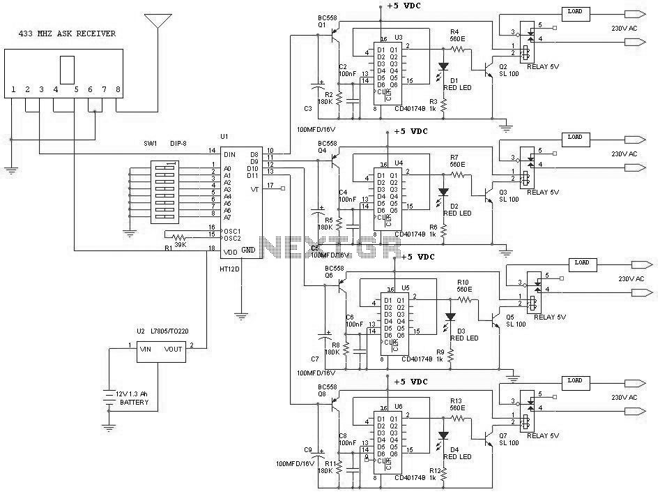
The receiver section consists of an ASK receiver operating at the same frequency (433.92 MHz) with a sensitivity of 3 µV. It operates within a voltage range of 4.5 to 5.5 volts DC and provides both linear and digital outputs. The receiver captures the data from the transmitter, and the decoder (HT12D) processes this data, enabling the corresponding output pins (pins 10, 11, 12, and 13). Each output pin connects to separate flip-flops, which toggle their states based on the encoder's output. The output of the flip-flop transitions from a low (reset) state to a high (set) state, generating a high signal.
Since the output signal from the flip-flop cannot directly drive a relay, a current driver is used. The SL100 transistor serves as the current driver, facilitating the connection of the appliance to a 230V AC power source through a relay. When the same button on the remote is pressed again, the output of the decoder returns to high, toggling the flip-flop state once more. This action re-energizes the relay, turning the appliance off.
This RF remote control system offers an efficient and straightforward approach to managing various home appliances wirelessly, enhancing user convenience and comfort.This is a simple type remote control by using RF communication without microcontroller. In this project a remote has been designed for various home appliances like television, fan, lights, etc. It gives lot of comfort to the user since we can operate it by staying at one place. We can control any of the appliances by using this remote within the r ange of 400 foots. In this project consist of two sections, transmitter (remote) and receiver section. Whenever we are pressing any key in the remote it generates the corresponding RF signals, and these signals are received by the receiver unit. ASK transmitter and receiver is used as transmitter and receiver. HT12E, HT12D encoders and decoders are used in this electronic circuit. The block digram of the whole circuit is given below. In remote section consist of an encoder (HT 12E) and a ASK transmitter. The encoder generates 8 bit address and 4bit data. We can set the address by using the DIP switch connected in A0 to A7 (pin 1 to 8 ) encoder. If we set an address in the remote section, the same address will be required in the receiver section.
So always set same address in transmitter and receiver. Whenever we press any key in the remote the encoder generates corresponding 4bit data and send this data with 8bit address by using ASK transmitter. The transmitting frequency is 433MHz. The transmitter output is up to 8mW at 433. 92MHz with a range of approximately 400 foot (open area) outdoors. Indoors, the range is approximately 200 foot. At the receiver section ASK receiver is present. The receiver also operates at 433. 92MHz, and has a sensitivity of 3uV. The ASK receiver operates from 4. 5 to 5. 5 volts-DC, and has both linear and digital outputs. It receives the datas from the transmitter. Then the decoder (HT 12D) decodes the date and it will enable the corresponding output pin (pin 10, 11, 12, 13).
Each output pins are connected to separate flip flops. The output of encoder will change the state of the flip flop. So its output goes to set (high) from reset (low) state. This change makes a high signal in the output of the flip flop. This output signal is not capable to drive a relay directly. So we are using current driver, SL100 transistor act as the current driver. The appliance is connected to 230V AC through the relay and the appliance will start. The relay will be re-energized when the same switch is pressed in the remote. This is because we are pressing the same switch in the remote control. The output of the decoder again goes to high so this signal will again change the state of the flip flop. So, the relay gets re-energized and the appliance goes to OFF state. 🔗 External reference
Related Circuits
This circuit controls a load, specifically a DC brushless fan, based on temperature compared to a setpoint. The transducer used is a diode operating in the forward polarization regime. When forward-biased, the forward voltage drop across the diode exhibits...
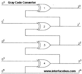
Gray Code is a positional binary number notation where any two numbers differing by one are represented by expressions that are identical except in one position, differing by only a single unit in that place. This code consists of...
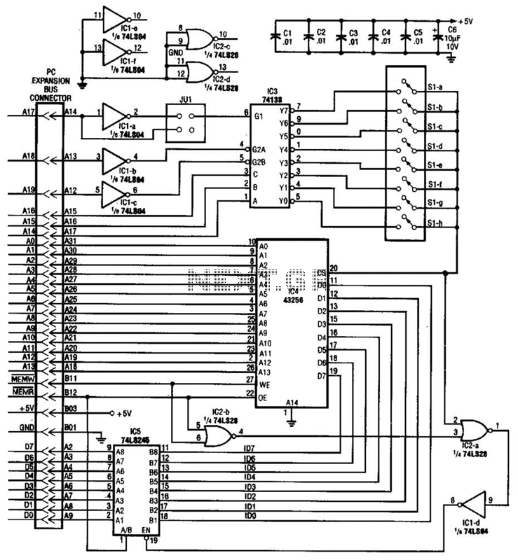
This circuit protects a PC by requiring a password to boot. After three unsuccessful attempts, the computer must undergo a cold reboot before the password can be attempted again. Software for this system is available; consult the reference for...
The following circuit illustrates a Radio Remote Control Circuit Diagram. This circuit is based on the UM91214B integrated circuit (IC) and features the use of DTMF (dual-tone multi-frequency) signaling. The Radio Remote Control Circuit utilizing the UM91214B IC is designed...
An LMX1601 Phase locked loop, a discreet FET VCO, and an AVR microcontroller combine to make a stable, easy to use monophonic FM transmitter that includes an audio activated switch that turns the transmitter on only when it is...

This design outlines a sensor circuit that utilizes an LED as a light sensor. The operational control and amplification of the output are managed by a 1458 integrated circuit (IC), which functions as an operational amplifier (op-amp). The circuit...