
dmm fuse protector

This circuit design serves as an effective solution for protecting the input of a digital multimeter by employing a current limiting mechanism rather than a traditional fuse. The core components include a resistor (R1), a power FET (T1), a secondary transistor (T2), and a buzzer for acoustic signaling.
The operation begins when the current through R1 approaches the 500 mA threshold. At this point, the voltage drop across R1 reaches 0.75 V, triggering T2. This action causes T1 to enter a state where it limits the current flowing through the load to approximately 500 mA, thus protecting the DMM from potential damage due to excessive current.
The selection of the power FET is crucial, as it must be capable of handling the expected power dissipation. The IRF740S is a robust option, but alternatives like the BUZ10 can also be employed for applications requiring higher power handling capabilities. The design includes a consideration for thermal management; if the power dissipation in the FET is expected to exceed 1-2 watts, appropriate heat sinks or cooling mechanisms must be implemented to prevent thermal failure.
For power supply, the circuit can operate with either a 12-V or a 9-V battery. The choice of battery affects the type of buzzer used; a 12-V buzzer is required for a 12-V battery, while a 9-V battery can utilize a matching buzzer or, if the buzzer is unnecessary, a 10-kΩ resistor can be used instead to maintain circuit integrity.
Overall, this current limiting circuit provides a reliable alternative to fuses, ensuring that the digital multimeter remains protected during use while also offering an audible warning to alert users of the current limiting action.Typically the input protection fuse of your DMM will blow in the middle of a demonstration or an exciting phase of your construction work. Spare fuses are always hard to find, and if available take a lot of time to install. This circuit replaces the fuse by a 500 mA current limiter. When resistor R1 passes about 500 mA, it will drop 0. 75 V which is sufficient to switch on T2. With the buzzer acting as a pull-up resistor (and, of course, as a very loud acoustic warning device), the voltage at the gate of power FET T1 will drop to a level at which the drain-source current is limited to a safe value of about 500 mA. Of course, the excess energy caused by the current limiting action is dissipated by the FET. Cooling is required in all cases where the dissipation can be expected to exceed about 1-2 watts. After all, without cooling, the voltage allowed to occur across the FET will be just 4V (2 W = 0. 5 A G— 4 V). Although an IRF740S is indicated in the circuit diagram, almost any power FET may be used. The popular BUZ10, for example, is a good choice when a lot of power has to be dissipated. If a 12-V mini battery is used then the buzzer should also be a 12-V device. However the circuit will also work ¬ne from the more commonly found (and certainly less expensive) 9-V battery and a matching buzzer.
If the latter is not required it is simply replaced by a 10-k resistor. 🔗 External reference
Related Circuits
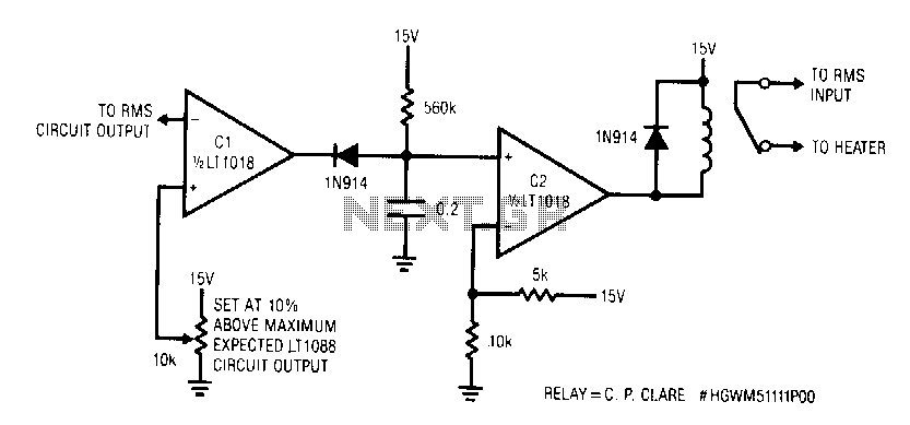
This circuit responds quickly enough to prevent damage from most overloads. Capacitor C1's input is connected to the output of the LT1088 servo circuit. If the LT1088 circuit's output exceeds the threshold at C1's other input, C1 trips, discharging...
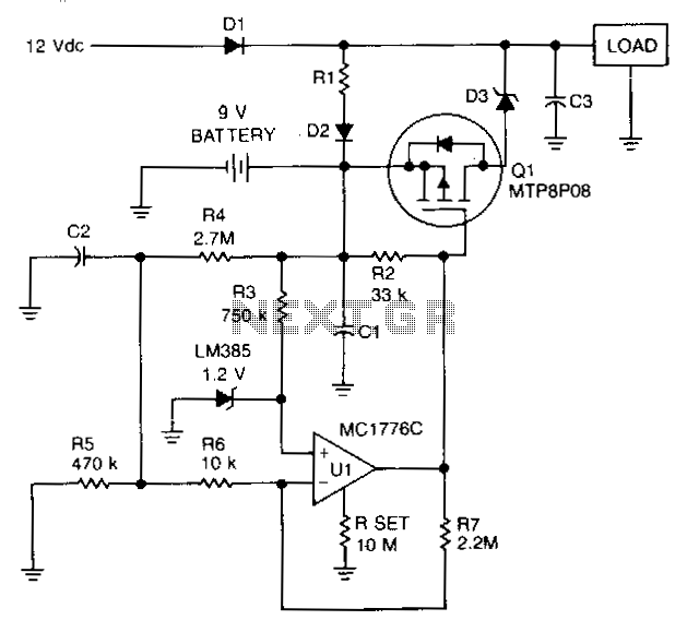
To prevent battery damage due to over-discharge, a low-voltage detector and switch should be included in the design of the battery backup circuit. The detector circuit should consume extremely low current. The switch should exhibit a low-voltage drop and...
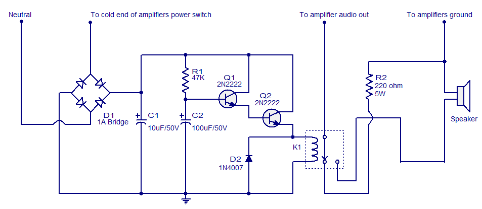
When the amplifier is powered on, the speaker experiences a sudden high voltage, resulting in a loud thud sound. This phenomenon is detrimental to the speaker and significantly shortens its lifespan. The circuit illustrated here connects the speaker to...
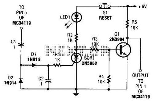
The ear protector is a peak audio detector and shutdown circuit that disables the amplifier through its chip-disable input when the output volume of the amplifier reaches a predetermined level. Although designed for the MC34119 amplifier, the circuit should...

This circuit produces a soft turn-on for halogen lamp filaments upon powering up. The MOSFET used is a BUZ10, which has a resistance of 0.2 ohms. Resistors R1, R2, and capacitor C1 set the turn-on rate, while diode D1...
The circuit is designed to prevent over-voltage conditions in a battery during charging. It operates automatically to charge and recharge with a very low power consumption of less than 20mA, making it suitable for use with batteries rated between...