
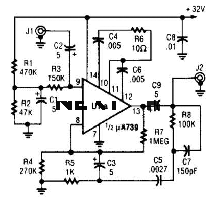
Low-noise 30Mhz preamplifier

The low-noise preamplifier circuit is designed to amplify weak signals while maintaining a minimal level of noise, making it suitable for applications where signal integrity is critical. The specified noise figure of 1 dB at 30 MHz indicates that the circuit introduces very little additional noise to the signal, which is essential for high-fidelity audio or sensitive RF applications.
The 3 dB bandwidth of 10 MHz suggests that the amplifier can effectively process signals within this frequency range, allowing it to handle various input signals without significant loss of amplitude or fidelity. The gain of 19 dB means that the output signal will be 19 dB stronger than the input, providing sufficient amplification for further processing stages.
The total current drain of 13 mA with a +10 volt supply reflects the efficiency of the circuit, as it operates within a low power range while delivering the necessary performance. The choice of 14-watt carbon resistors indicates a robust design capable of handling higher power levels without overheating, ensuring reliability during operation.
The use of 50-volt ceramic bypass capacitors is also noteworthy, as these components serve to filter out high-frequency noise and stabilize the power supply, contributing to the overall performance of the preamplifier. Proper bypassing is crucial in maintaining signal integrity and preventing oscillations within the circuit.
Overall, the specifications and component choices reflect a well-engineered low-noise preamplifier suitable for various electronic applications, emphasizing both performance and reliability.Low-noise preamplifier has a noise figure of 1 dB at 30 MHz and 3 dB bandwidth of 10 MHz. Gain is 19 dB Total current drain with a +10 volt supply is 13 mA JMl resistors are 14 watt carbon; bypass capacitors are 50-volt ceramics.
Related Circuits
JFET iPod preamplifier, DIY Hi-Fi, schematic The JFET iPod preamplifier circuit is designed to amplify the audio signal from an iPod or similar portable audio device, enabling it to drive higher impedance loads such as amplifiers or speakers. This circuit...
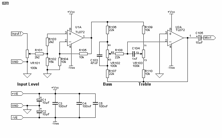
The mixer is the common "virtual earth" mixing amplifier, and there is nothing special about it. Note that it is inverting, which complements the tone controls (also inverting) so the absolute signal polarity is maintained. As shown, the mixer...
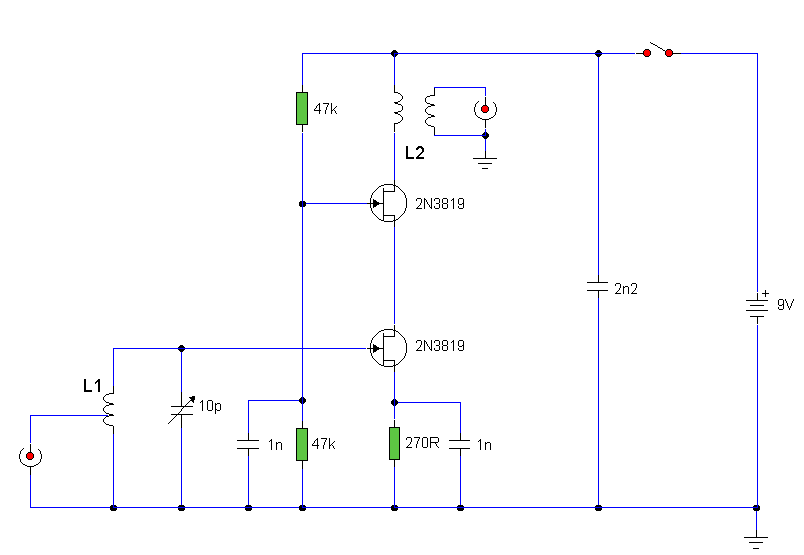
The circuit utilizes two 2N3819 FETs arranged in a cascode configuration. The lower FET functions in common source mode, while the upper FET operates in common gate mode, achieving full high-frequency gain. The lower FET is tunable, enabling peak...
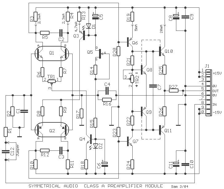
The preamplifier that appears in the figure is a completely symmetrical preamplifier, from the input as the exit and it works in Class A. It does not have somebody innovation, simply it uses good solutions, in order the result...
A fundamental component for audio applications, this circuit functions as a general-purpose preamplifier. It is recommended to utilize two circuits for stereo configurations. This audio preamplifier circuit is designed to amplify low-level audio signals, making it suitable for a variety...
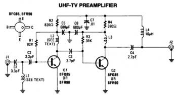
This is a low-cost, antenna-mounted UHF TV pre-amplifier circuit that can provide more than 25 dB of gain. The first stage of the pre-amplifier is biased for optimum gain. L1 and L2 are strip line equivalents with a length...