
Electronic Gong Circuit
The electronic gong circuit operates by generating a sound through a combination of oscillation and filtering techniques. The oscillator, formed by the NAND gate, functions as an astable multivibrator, producing square wave pulses at a defined frequency. These pulses are then fed into the twin-T filter, which is designed to selectively allow certain frequencies to pass while attenuating others. The twin-T filter configuration consists of resistors and capacitors arranged to create a notch filter effect, enabling the production of a specific damped sinusoidal waveform that mimics the sound of a gong.
The TL081 operational amplifier serves as the active component in the twin-T filter, enhancing the circuit's ability to produce a clear and distinct tone. The output of the filter is then sent to an audio amplifier, such as the LM386N, which amplifies the signal to drive a speaker or other audio output device. This amplification stage is crucial for ensuring that the sound produced by the circuit is loud enough to be heard clearly.
The component values play a significant role in determining the performance characteristics of the electronic gong. Capacitor CI is responsible for setting the rate of oscillation, influencing how quickly the circuit produces sound. Capacitors C2 and C3 are pivotal in adjusting the frequency of the gong sound, allowing for customization based on user preferences or specific application requirements. The adjustment of resistor R1 is also essential, as it fine-tunes the tone quality, enabling the user to achieve the desired sound effect.
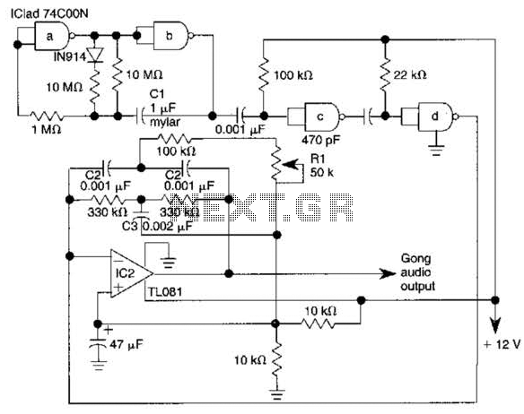
In summary, the electronic gong circuit is a sophisticated assembly of components that work together to create a unique sound. The careful selection and adjustment of each component ensure that the circuit can produce a range of tones and frequencies, making it versatile for various applications. The electronic gong is comprised of an oscillator (built around half of a 74COON quad 2-input NAND gate), an active twin-T filter (built around a TL081), and will drive an audio amplifier IC such as aii LM386N. Pulses from astable multivibrator ICl cause the twin-tee active filter U2 to ring, producing a damped sinusoidal output.
CI varies rate and C2-C3 vary gong frequency. Adjust Rl for best tone sound. 🔗 External reference
Related Circuits
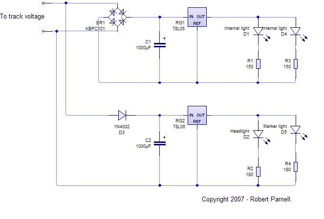
An LED, or Light Emitting Diode, is a semiconductor device that allows current to flow in one direction while blocking it in the opposite direction. This characteristic makes LEDs polarized components, having a positive side known as the anode...
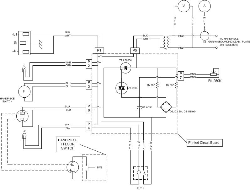
The most challenging aspect of the build was to find or design a circuit capable of handling the load while remaining within budget. This circuit achieves both objectives. It adjusts the power output using a potentiometer (variable resistor) R1,...
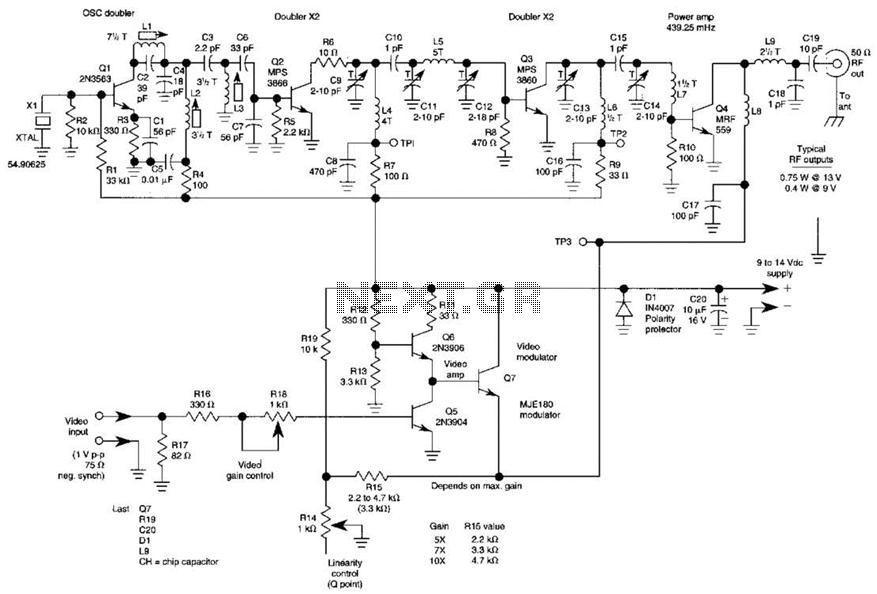
The three schematics illustrate three building blocks for a 10-meter SSB transmitter. These blocks can also be utilized independently as circuit modules for other transmitters. The VFO board incorporates an FET transmission oscillator, with the VFO signal being mixed...
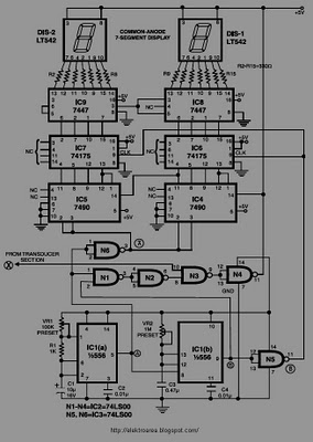
This circuit is designed to display the speed of a vehicle in kilometers per hour (km/h). An opaque disc is mounted on the spindle connected to the front wheel of the vehicle. The disc features evenly spaced holes along...

A simple transistor amplifier circuit diagram and schematic that can be used as a 12-watt audio transistor amplifier. An operational amplifier (op-amp) integrated circuit (IC) is used to produce the required gain. This circuit is designed to amplify audio signals,...
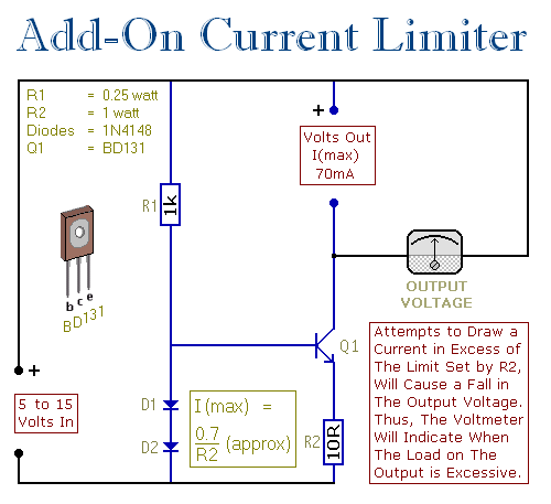
This circuit allows setting a limit on the maximum output current from a power supply unit (PSU). It is particularly useful when powering up a project for the first time or conducting a soak test. By establishing an upper...
Warning: include(partials/cookie-banner.php): Failed to open stream: Permission denied in /var/www/html/nextgr/view-circuit.php on line 713
Warning: include(): Failed opening 'partials/cookie-banner.php' for inclusion (include_path='.:/usr/share/php') in /var/www/html/nextgr/view-circuit.php on line 713