
TYPICAL TRANSISTOR CIRCUIT

The described circuit utilizes a silicon transistor, characterized by its forward base/emitter voltage range of 0.6 to 0.7 volts. This voltage range is crucial for identifying the type of transistor in use. In this instance, the calculation of the forward bias voltage is conducted by subtracting the emitter voltage (1.9 V) from the base voltage (2.6 V), resulting in a forward bias of 0.7 V. This confirms that the transistor is indeed a silicon type, as opposed to a germanium transistor, which typically operates with a forward bias voltage of 0.2 to 0.3 V.
In practical applications, understanding the operating characteristics of silicon transistors is essential for designing reliable electronic circuits. Silicon transistors are favored in many applications due to their higher thermal stability and better performance in high-frequency environments compared to germanium transistors.
When designing circuits that incorporate silicon transistors, it is important to consider parameters such as the transistor's current gain, maximum collector current, and the thermal resistance. Additionally, biasing arrangements must be carefully designed to ensure that the transistor operates within its optimal range, preventing distortion and signal loss. Proper impedance matching is also vital to maximize power transfer and minimize reflections in RF applications.
Further exploration into transistor amplifier bias arrangements, specifications, and parameters will enhance the understanding of transistor functionality and design principles, allowing for the creation of more complex and efficient electronic equipment.This is a silicon transistor circuit showing typical voltage values. When the forward base/emitter voltage is 0.6 to 0.7 V, the transistor is silicon. Germanium transistors will have a forward base/emitter bias voltage of 0.2 to 0.3 V This is a silicon transistor because 2.6 base volts minus 1.9 emitter volts equal a forward bias of 0.7 volts indicating a silicon transistor.
🔗 External reference
Related Circuits

A simple alarm circuit with a diagram and schematic that generates a multi-tone sound. This alarm circuit is suitable for use in burglar alarms and sirens and is designed using dual op-amps MC1458 and LM380. The described alarm circuit utilizes...
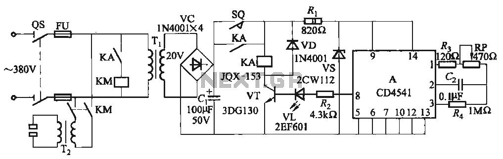
One Foot Spot Welder circuit. The circuit utilizes the IC CD4541 to provide precise delay characteristics, enabling the electrical time constant necessary for effective welding. This ensures consistent welding quality across identical weldments. For varying weldments, the electrical locator...
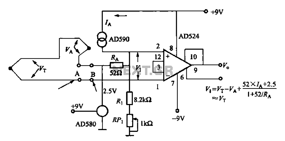
The AD524J type thermocouple cold junction temperature compensation circuit is illustrated in Figure 1-20. This circuit utilizes J-type thermocouples, with the base reference voltage sourced from the AD580, an integrated temperature sensor, and the precision instrumentation amplifier AD524. The...
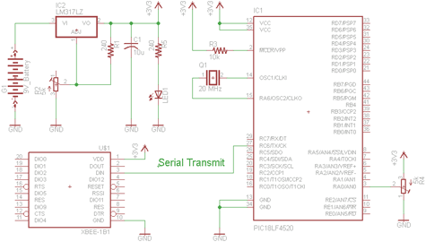
There are two schematics to examine for constructing a transmitter/receiver system. The first schematic is the transmitter, featuring a variable trimpot connected to RA0. The trimpot's value will be transmitted from the Tx pin of the PIC to the...
After conducting experiments with a rotary encoder connected directly to keyboard switches, it was found that the keyboard controller IC (an Intel P8049AH in this case) is unable to detect pulses that are too narrow. Testing involved rotating the...

A micro mixer circuit is designed to be simple, affordable, compact, and versatile. This circuit can mix up to four input channels, including microphone signals, FM tuners, AUX, and other signals, as illustrated in Figure 1. The operation begins...