
Electronic Lockers
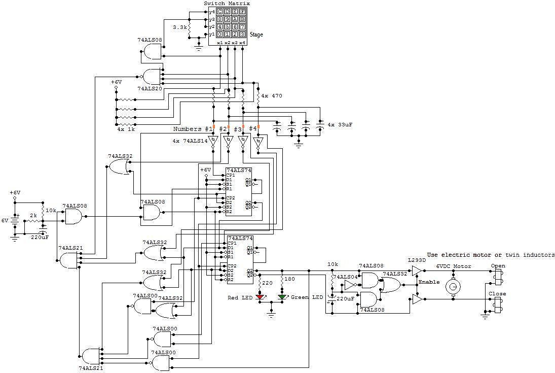
The electronic locker circuit is designed to provide secure access through a coded switch matrix, making it a practical solution for various applications requiring controlled access. The switch matrix comprises 16 tactile switches arranged in a grid, allowing for easy user interaction. The design leverages a 7408 quad two-input AND gate, which processes the inputs from the switch matrix to validate the entered code against the preset combination.
The choice of using a 3.3k resistor in the circuit is important for limiting current and protecting the inputs of the 7408. The design also includes a feedback mechanism through the LEDs, providing visual confirmation of the lock status. The red LED indicates that the locker is secure, while the green LED signals successful unlocking.
For the locking mechanism, the use of a motor or inductors is a critical design decision. The motor-driven mechanism offers a robust solution for moving the locking bar, while the inductor-based system provides a potentially more compact and efficient alternative. The L293D motor driver allows for bidirectional control of the motor, facilitating both locking and unlocking functions.
The power supply design emphasizes the use of a rechargeable 6V battery, promoting sustainability and cost-effectiveness. This choice is vital for applications where the locker may be used frequently, as it ensures that the system remains operational over extended periods without the need for constant battery replacement.
Overall, this electronic locker circuit exemplifies an efficient integration of components to achieve a reliable access control system, suitable for various environments such as homes, offices, or secure storage facilities.This circuit is an Electronic Locker. It is controlled by a switches combination (by a code). There is a switch matrix on the door of the locker. This one is a unit of switches connected into 4 arranged of 4 columns for a total of eight terminals. When we press on a switch, this one establishes the contact between its column and its line. This swi tch matrix is also used in the telephones, for example. But it is numbered from 0 to 9 and from A to F for a total of 16 switches. To open the locker, we have to press 4 specific and different switches in the good order. If for example the code is 0, 1, 2, 3 and we press two times to the same switches: 0, 1, 2, 2, 3 the locker won`t open. In this circuit, the code is 0, 1, 2, 3 but we can set the desired code when we built de circuit. The desired line (called "stage" in the schematic) is connected to the ground and to a pin of the 3. 3k resistor and the other line is connected to an input of the 7408 and to the other pin of the resistor.
All the desired numbers of the code are in the same line. To set the order of the number of the code, we have to set the good connection between the node of the 7414 input and the appropriate node of the capacitor. For example, if we select the first line (y1) and the code is 0, 1, 2, 3 the first number (#1) is connected to the top left contact (x1).
The switch 0 is corresponding to x1/y1. These points of contact are colored in orange in the schematic. When the locker is locked, the red LED is turned on and the green LED is turned off. When the locker is opened, the red LED is turned off and the green LED is turned on. To lock the locker, we can push any of the 16 switches of the matrix. The locker is powered by a 6V source. I recommend using a 6V rechargeable battery because this one lasts a long time (at least 3 full days) and can be re-used. Otherwise, we can use four 1. 5V battery connected in serial. These least only 5 hours but are less expensive. To save energy, we can remove the red LED. When the locker is powered on, it is locked. The electric motor or the inductors close the door while a bit of time and after, stop working. When we open the locker, the electric motor or the inductors open the door while a bit of time and after, stop working.
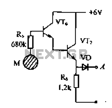
To control the state of the door (open or lock) we can use an electric motor or a pair of inductors. If we use a electric motor, when the locker is closed, the motor turns in the anti-clockwise direction during a certain time and moves down a toothed bar. After this time, the motor stops turning and the locker remains closed. When the locker is opened, the motor turns in the clockwise direction during a certain time and moves up the toothed bar.
After this time, the motor stops turning and the locker remains opened. If we use two inductors, when the locker is closed, the second inductor works during a certain time and moves left a magnetic bar by attraction. After this time, the inductor stops working and the locker remains closed. When the locker is opened, the first inductor works during a certain time and moves right the magnetic bar.
After this time, the inductor stops turning and the locker remains opened. The buffer (L293D) who controls the motor or the inductors has two Vcc inputs and four ground connections. The both Vcc inputs must be connected to the +6V and all ground connections must be connected to the ground of the circuit.
All the parts of the circuits are placed in the rack except the DELs and the switch matrix which them, are placed on the door. 🔗 External reference
Related Circuits
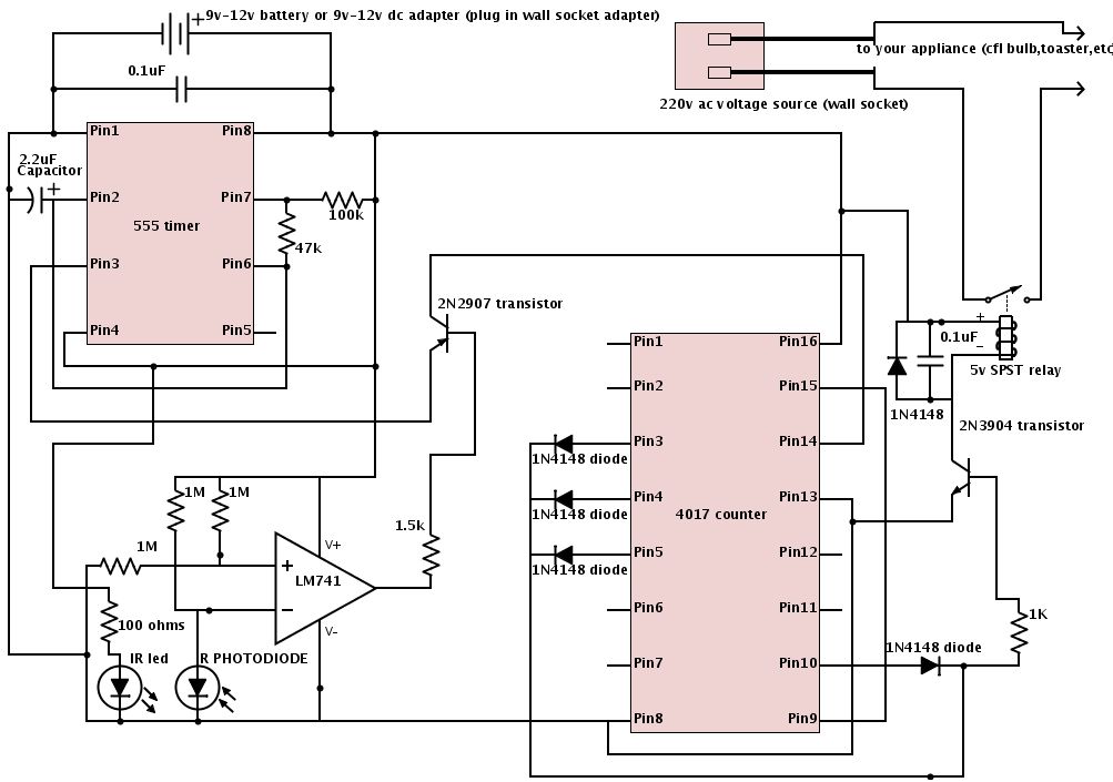
The schematic is provided below. It is recommended to construct it in three distinct sections, similar to the method demonstrated. The 555 timer circuit: connect pin 2 to pin... The schematic outlines a circuit design utilizing a 555 timer, a...
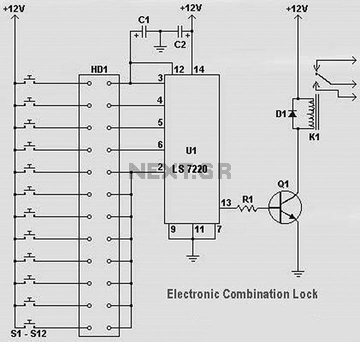
The following diagram illustrates a straightforward electronic combination lock utilizing the IC LS7220. The component part list includes: C1 = 1µF 25V, C2 = 220µF 25V, R1 = 2.2K Ohm, Q1 = 2N3904 or 2N2222, D1 = 1N4148 or...
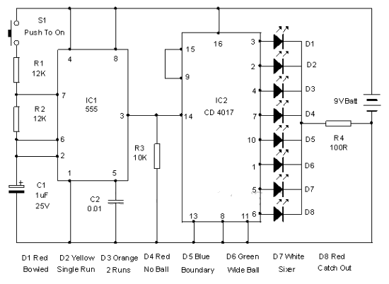
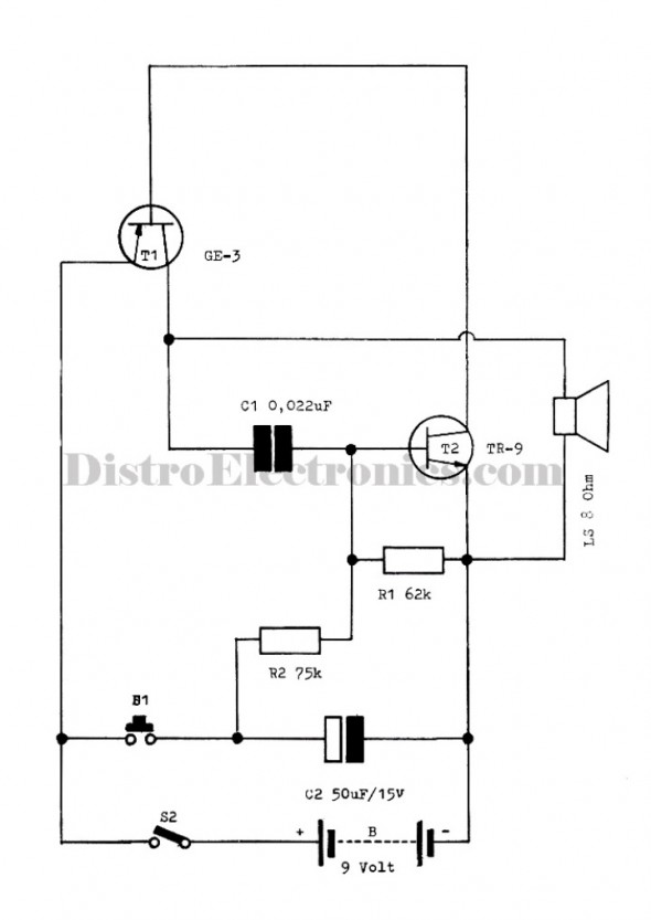
This electronic cricket device is a gift for children. This simple battery-powered circuit can be used to simulate a cricket match with friends. Each LED in the circuit represents various statuses of the cricket match, such as a six,...
Delay electronic doorbell circuit - touch doorbell amplifier circuit The delay electronic doorbell circuit is designed to provide a user-friendly interface for doorbell activation, utilizing a touch-sensitive amplifier circuit. This circuit typically incorporates a touch sensor that detects user interaction,...
The following circuit illustrates the electronic diagram design for police and ambulance alarms. Features include simplicity and ease of assembly, as well as cost-effectiveness. This electronic schematic represents a basic alarm system intended for use in police and ambulance applications....
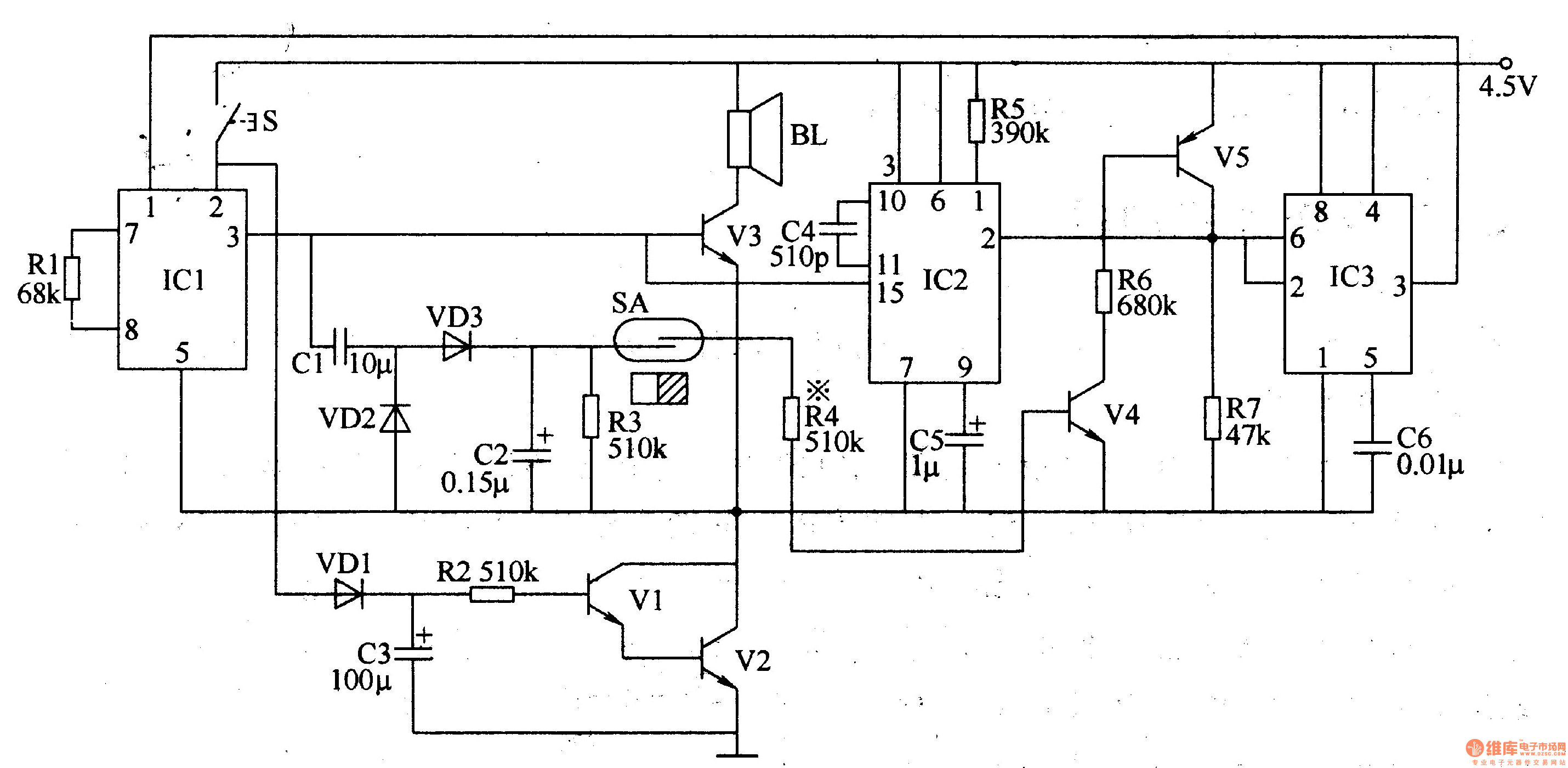
The electronic doorbell circuit is designed to provide a polite and welcoming sound upon activation. It consists of several key components, including a trigger control circuit, an audio amplifier output circuit, a music circuit, and a voice delay control...
Warning: include(partials/cookie-banner.php): Failed to open stream: Permission denied in /var/www/html/nextgr/view-circuit.php on line 713
Warning: include(): Failed opening 'partials/cookie-banner.php' for inclusion (include_path='.:/usr/share/php') in /var/www/html/nextgr/view-circuit.php on line 713