
Reading Schematics

Understanding and interpreting schematic diagrams is fundamental for anyone involved in electronics. A schematic serves as a visual representation of an electrical circuit, detailing how components are interconnected. Each symbol in the schematic corresponds to a specific component, such as resistors, capacitors, and transistors, while lines represent the conductive paths (wires) between these components.
In practice, schematic diagrams follow standardized symbols as defined by organizations such as the Institute of Electrical and Electronics Engineers (IEEE) and International Electrotechnical Commission (IEC). This standardization facilitates communication among engineers and technicians, allowing for a universal understanding of circuit designs.
When analyzing a schematic, it is crucial to identify the power source and the ground reference. The power source typically provides the necessary voltage for the circuit's operation, while the ground serves as a common return path for current. Proper grounding is vital for circuit stability and performance, especially in sensitive applications like audio and radio frequency circuits.
Moreover, attention should be paid to the polarity of components, particularly diodes and electrolytic capacitors, which must be connected correctly to avoid circuit failure. The orientation of these components is usually indicated in the schematic with symbols or markings.
In summary, a thorough understanding of schematic diagrams is essential for designing, troubleshooting, and modifying electronic circuits. By following established conventions and guidelines, engineers can effectively communicate complex ideas and ensure the reliable operation of electronic systems.This page was created in response to all the email I receive, on how to read a schematic. Learning to read a schematic diagram, is similar to map reading. You need to know which wires connect to which component and where each wire starts and finishes. With a map book this would be equivalent to knowing your origin and destination points and which roads connect to the motorway network, etc. However schematics are a little more complicated as components need to be identified and some are polarity conscious (must be wired up in the circuit the correct way round) in order to work. You do not need to understand what the circuit does, or how it works, in order to read it, but you do need to correctly interpret the schematic.
Here are some basic rules that will help with reading a diagram. Look at the circuit diagram shown below: The blue lines represent wires and for simplicity i have labeled them as A, B, C. There are just three components here and it is easy to see where each wire starts and ends, and which components a wire is connected to.
As long as the wire labelled A connects to the switch and negative terminal of the battery, wire B connects to the switch and lamp, and C connects to the lamp and the battery positive terminal then this circuit should work. Before moving on, it is important to realise that any schematic may be drawn in a number of different ways.
In Fig 1 and Fig 2 i have drawn two electrically equivalent lamp dimmer circuits, they may look very different, but in fact, if you mentally label the wires and trace them, you will see that in both diagrams each wire starts and finishes at the same components on both diagrams. The components have been labelled and so have the three terminals of the transistor. In Fig1 there are two wire junctions as indicated by a "dot". A wire cpnnects from battery positive to the C (collector) terminal of the transistor, and also a wire runs from the collector terminal to one end of the potentiometer, VR1.
The wires could be joined at the transistor collector, battery positive or even one end of the potentiometer, it does not matter, as long as both wires exist. Similarly, a wire runs from battery negative to the lamp, and also from lamp to the other end of VR1.
The wires could be joined at the negative terminal of the battery, the lamp, or the opposite tag of VR1. In drawing Fig 1, I could have drawn the wires from the lamp and bottom terminal of VR1 back to the battery negative terminal and placed the dot there, it would still be the same.
If you now look at Fig 2, you will see that one wire junction appears at the negative battery terminal, the other junction in a similar place. Sometimes the way a circuit is wired up may compromise its performance. This is particularly important for high frequency and radio circuits, and some high gain audio circuits.
See the diagram below: Although this audio circuit has a voltage gain of less than one, wires to and from the transistor, should be kept as short as possible. This will prevent a long wire picking up radio interfereance or mains hum from a transformer. Also, in this circuit input and output terminals have been labelled and a common reference point or earth is indicated.
The earth terminal would be connected to the chassis or metal framework of the enclosure in which this circuit is built. Many schematics contain a chassis or earth point. Generally its just to indicate the common reference terminal of the circuit, but in radio work, the earth symbol usually requires a physical connection to a cold water pipe or an earth spike buried in the soil.
🔗 External reference
Related Circuits
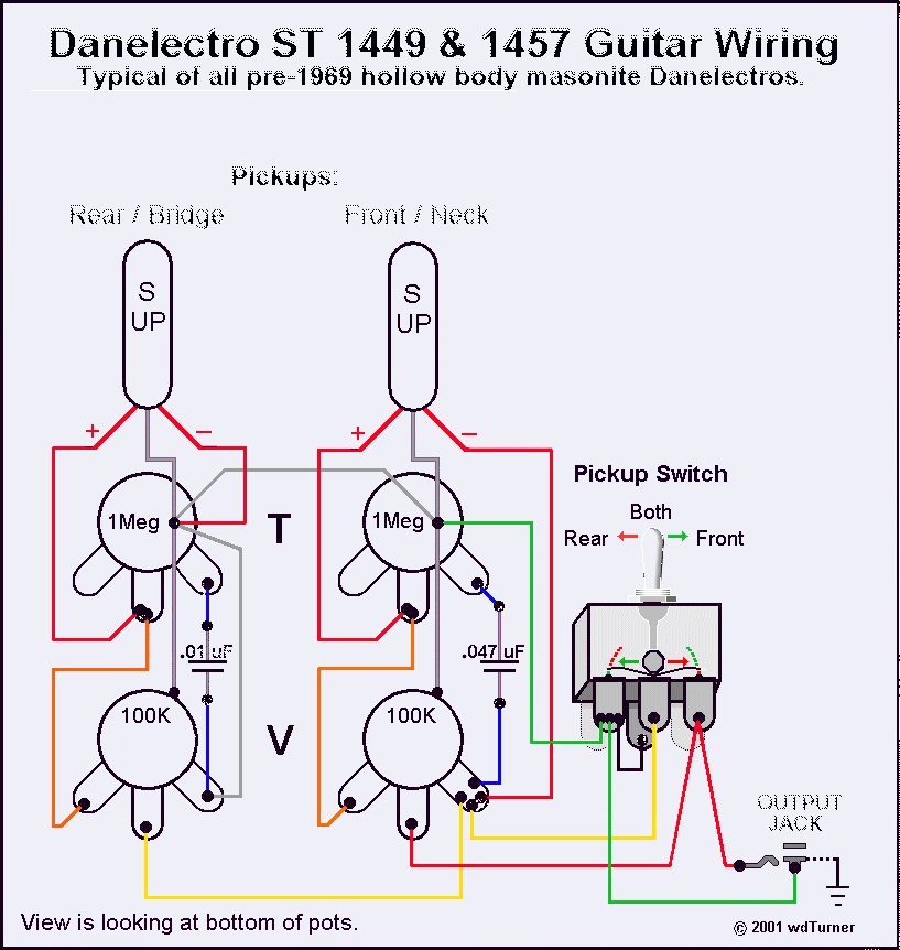
Using a magnetic compass, ensure that both pickups have a South polarity on the top of each pickup. Verify this by checking for a North polarity on the bottom of the pickups. It is uncommon to find both pickups...
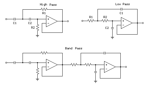
The figures below illustrate using opamps as active 2nd order filters. Three 2nd order filters are shown, low pass, high pass, and bandpass. Each of these filters will attenuate frequencies outside their passband at a rate of 12dB per...
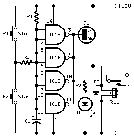
This timer is designed to automatically switch off a portable radio after a set period, allowing users to relax without worrying about battery drain. Resistor R1 and capacitor C1 create a long time constant. When switch P2 is momentarily...
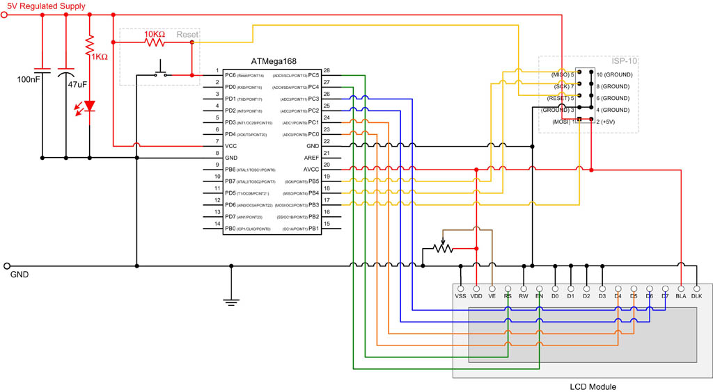
EEPROM (Electrically Erasable Programmable Read-Only Memory) is non-volatile memory, meaning it retains data even after power is removed. The ATmega168 microcontroller includes 512 bytes of EEPROM, which can be utilized to store system parameters and small amounts of data....
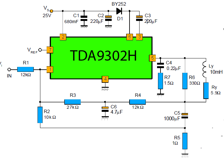
The TDA9302H is a monolithic integrated circuit housed in a HEPTAWATTTM package. It functions as a high-efficiency power amplifier designed for direct drive vertical deflection coils in television yokes. This component is suitable for use in both color and...
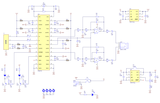
Creating a sound card is no longer a complex task. By utilizing the PCM2702 integrated circuit from Burr Brown / Texas Instruments, it is possible to design a fully functional USB sound card. This sound card can be powered...