
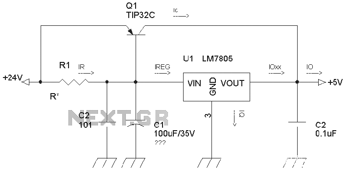
Three-terminal linear regulator expansion flow circuit diagram
1. Disadvantages of this power supply:
1.1 This power supply is a linear regulator circuit, which inherently has unique internal power losses. All voltage drops are converted into heat, resulting in low efficiency; therefore, heat management is critical.
1.2 The core component, the 7805, has a relatively low operational speed, leading to slow responses to abrupt changes in input voltage or load current.
1.3 This circuit lacks overcurrent and temperature protection for the 7805 itself, and the expansion flow transistor TIP32C is unprotected. This presents a significant drawback; if the 7805 enters a protection state, the output circuit will experience a voltage drop of Vin - Vce, resulting in an output lower than expected.
2. Advantages of the power supply:
2.1 The circuit is simple, stable, and easy to commission, requiring minimal debugging.
2.2 It is cost-effective, making it suitable for budget-sensitive products.
2.3 The circuit exhibits minimal high-frequency or low-frequency signal radiation, making it easier to control electromagnetic interference (EMI).
3. Circuit operation:
Io = Ioxx + Ic, where Ioxx = IREG - IQ (IQ is the quiescent current of the 7805, typically 4-8 mA). The current IREG is defined as IR + Ib, where IR = VBE / R1 (with VBE being the base-emitter voltage of the TIP32 for turn-on). Therefore, Ioxx can be expressed as:
Ioxx = IREG - IQ = IR + Ib - IQ = VBE / R1 + Ic / - IQ.
Given that IQ is quite small, it may be omitted, leading to:
Ioxx = VBE / R1 + Ic /
For example, with VBE = 1.2V and R1 = 22Ω, the equation simplifies to:
Ioxx = 1.2 / 22 + Ic / 10 = 0.0545 + Ic / 10.
Assuming Ioxx = 100 mA, Ic can be calculated as:
Ic = 10 * (Ioxx - 0.0545) = 455 mA.
Thus, the total output current Io = Ioxx + Ic = 100 + 455 = 555 mA.
If Ioxx = 200 mA, then Ic = 10 * (200 - 0.0545 * 1000) = 1955 mA, resulting in Io = 200 + 1955 = 2155 mA. This demonstrates that the output current can be significantly improved.
3.2 The size of the resistance R is crucial; it directly influences the current through the 7805. A larger resistor value results in a smaller current flowing through the 7805, and vice versa. However, for circuits of this nature, the expansion flow transistor TIP32 typically requires an additional heat sink, while the 7805 may not need one. The resistor value must not be excessively large, adhering to the condition: R < VBE / (IREG - IB).
3.3 The input capacitance values for the 7805 circuit can lead to errors. Analysis has shown that surges in instantaneous output power can exceed 5V, potentially damaging the circuit. To mitigate self-excited oscillation in the 7805, a capacitor value of 0.33µF is commonly recommended. In commercial applications, it is noted that a 100µF capacitor is not necessary, and thousands of products have successfully utilized this configuration. This conclusion was reached after discussions regarding a new model that changed capacitance parameters, which resulted in surge issues and damage to peripherals, necessitating further analysis.Circuit is a very common three-terminal linear regulator expansion flow circuit, when we actually use, because there is no encounter some well-considered or is lower false failures. 1. First, it says disadvantage of this power 1.1 This power is a linear regulator circuit, all have their unique internal power loss, all the pressure drop is converted to heat loss, low efficiency, so pay special attention to heat issues. 1.2 Since the operation speed of the core member 7805 is not too high, so that the input voltage or the load current changes abruptly slow response.
1.3 This circuit does not increase the power supply protection circuit 7805 itself overcurrent and temperature protection but no expansion flow transistor TIP32C unprotected, there is a big drawback, if after 7805 to protect the state, the output circuit will be Vin-Vce, circuit output than expected, pay special attention to this point. 2. Power advantage 2.1 circuit is simple, stable and easy commissioning (almost no debugging). 2.2 cheap, suitable for cost demanding products. 2.3 circuit almost no high frequency or low frequency components of the signal radiation, low frequency, EMI, etc.
easy to control. 3. The circuit works Io = Ioxx + Ic. Ioxx = IREG - IQ (IQ 7805 for the quiescent current, typically 4-8mA) IREG = IR + Ib = IR + Ic / ( is TIP32C current magnification) IR = VBE / R1 (VBE TIP32 base for the turn-on voltage) So Ioxx = IREG - IQ = IR + Ib - IQ = VBE / R1 + IC / - IQ Because IQ is very small, it may be omitted, then: Ioxx = VBE / R1 + IC / Check TIP32C Manual, VBE = 1.2V, it is preferable 10 Ioxx = 1.2 / R + Ic / = 1.2 / 22 + Ic / 10 = 0.0545 + Ic / 10 (here take the main map in 22 OHM) Ic = 10 * (Ioxx - 0.0545) Assuming Ioxx = 100mA, Ic = 10 * (100 - 0.0545 * 1000) = 455 (mA) Then Io = Ioxx + Ic = 100 + 455 = 555 mA. Suppose Ioxx = 200A, Ic = 10 * (200 - 0.0545 * 1000) = 1955mA Io = Ioxx + Ic = 200 + 1955 = 2155mA Examples can be seen from the above two, the output current is greatly improved.
3.2 size of resistance R R to adjust the size of a great relationship through 7805 current, different values into the formula to see the bigger .R, the situation is the same output current flowing through the current 7805 to be smaller, and vice versa . However, generally such circuits, for expansion flow transistor TIP32 additional heat sink, and no need for 7805, but the value of R can not be too large, with the proviso that: R <VBE / (IREG - IB).
3.3 7805 circuit input capacitance values is an error, a friend already analyzed, mainly cause a surge in the instantaneous output power is far greater than 5V, the subsequent damage to the circuit. When in actual use, in order to suppress the self-excited oscillation of 7805, this capacitor is usually taken 0.33uF (most common spec.
are recommended for this parameter) This circuit is used in a commercial device, the real argument is not a 100uF capacitor circuit in addition to that, and the main paste the parameters, there are thousands of sets of products into the market, proved that it can be used. The reason is because open discussion posted colleagues used a new model, we change this parameter capacitance, surge caused the problem, and burned a lot of peripherals, and therefore re-analyzed.
Related Circuits
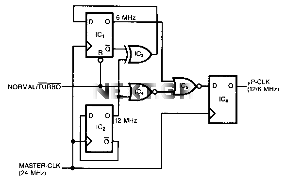
This circuit generates a dual-speed clock for personal computers. It synchronizes asynchronous switch inputs with the master clock to provide glitch-free transitions between clock speeds. The dual-speed clock allows certain programs to operate at a higher clock speed for...
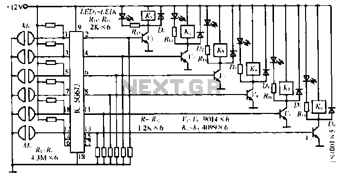
A, B, and C are used for a high-power split-phase system. The A + B' C' arrangement serves as a phase line for a range generator. The A-A' indole path string includes two 220V / 15W bulbs, which are...
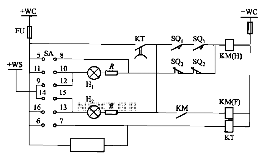
The BT9404 is a de-excitation type switch utilized with CJ4-S contactors and JT3-21/3-type electromagnetic relays. The control circuit is depicted in Figure 7-55. The KM contactors used are CJ4-S, while the time relay is the JT3-21/3. The SA component...
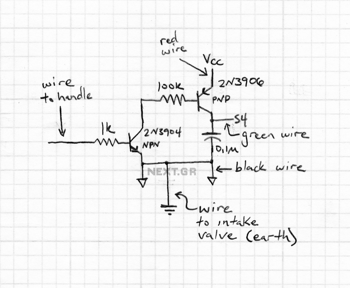
Magnetic stripe reader, electric circuit theory, logic operation. The wiring diagram does not connect the transistor in the circuit. The collector pin of the transistor connects to the tip pin of the jack. The base pin of the transistor...
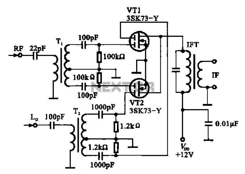
A balanced mixer circuit is illustrated using two dual-gate field effect transistors (FETs). The RF signal is coupled to the gates of these transistors through an input signal transformer (T1). Additionally, a local oscillation signal is introduced to the...
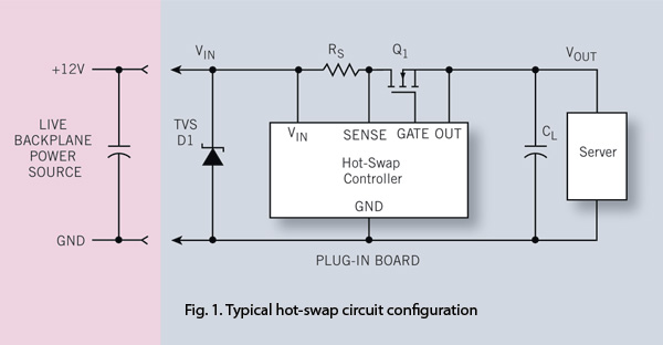
To ensure reliability, the server system designer must take into account the parasitics of hot-swap circuits and their associated transient behavior. It is recommended that a transient voltage suppressor (TVS) diode clamp be utilized at the line card input....
Warning: include(partials/cookie-banner.php): Failed to open stream: Permission denied in /var/www/html/nextgr/view-circuit.php on line 713
Warning: include(): Failed opening 'partials/cookie-banner.php' for inclusion (include_path='.:/usr/share/php') in /var/www/html/nextgr/view-circuit.php on line 713