
Electronic Thermometer

The described thermometer circuit employs a diode-connected 2N3904 transistor as a temperature sensor, leveraging its characteristics to provide an analog voltage output that correlates with temperature changes. The transistor's behavior is critical; as temperature rises, the forward voltage drop across the diode-connected base-emitter junction decreases, resulting in a measurable change in output voltage. This voltage change is translated into a current change at pin 3 of the first operational amplifier (IC1), which operates with a gain of 5, amplifying the signal for further processing.
The second operational amplifier (IC2) is configured as an inverting amplifier, allowing for the manipulation of the output signal to correspond with the desired current output. The feedback resistors R5 and R6 play a crucial role in determining the gain and stability of this amplifier, ensuring the circuit operates within the expected parameters. The calibration process is essential for accuracy, as it aligns the output current with specific temperature readings. By adjusting R6 when the sensor is submerged in an ice-point bath, the circuit can be fine-tuned to ensure that the meter reflects the true temperature accurately.
The use of twisted wire connections minimizes noise and interference, which is vital in sensitive analog circuits, particularly those measuring small voltage changes. The arrangement of resistors R4, R5, and R6 ensures that the circuit maintains a balance between the measured current and the expected output, providing a linear response across the specified temperature range. The design's simplicity, combined with the operational amplifiers' versatility, allows for a reliable and effective temperature measurement solution suitable for various applications. This thermometer is capable of measuring temperatures from - 30 to +120 °F. A diode-connected 2N3904 transistor form s a voltage divider with Rl, The transistor is used as the temperature sensor and, for best results, it should be connected to the rest of the circuit with twisted wire, as shown. As temperature increases, the voltage drop across the transistor changes by approximately -1.166 mV/°F.
As a result, the current at pin 3 of IC1, a 741 op amp with a gain of 5, decreases as the temperature measured by the sensor increases. A second 741 op amp, IC2, is configured as an inverting amplifier. Resistors R5 and R6 are used to calibrate the current. At a temperature of about -30°F, the current through R4 (formed by connecting a 910- and a 1600- resistor in parallel) should equal the current through R5 and R6.
A temperature of - 30°F will result in a meter reading of 0 mA, while a temperature of 120 °F will result in a meter reading of 1 mA. Divide the scale between those points into equal segments and mark the divisions with the appropriate corresponding temperatures.
If you divide it into 150 equal segments, for instance, each division will equal one degree. Calibration is completed by placing the sensor in an environment with a known temperature, such as in an ice-point bath. The freezing point of water is approximately 32°F. Verify that the temperature is indeed 32°F using another thermometer that is known to be accurate. Then, simply place the sensor in the bath and adjust R6 until you get the correct meter reading.
Related Circuits

This is a new design for a universal gear indicator that can be fitted to any motorcycle as an aftermarket accessory. Its main advantage is that its operation depends entirely on the gear shift lever movement, instead of connecting...

This thermometer utilizes an NTC thermistor (RIO) to generate a DC voltage that decreases with temperature, which in turn drives an integrated circuit (IC) that activates one of the 16 LEDs based on this voltage. R1 is a light-dependent...
This amplifier is designed for TV transposers and transmitters. It incorporates microstrip technology and discrete linear push-pull transistors with gold metallization and diffused emitter ballast resistors to enhance ruggedness and reliability. The unit is fully assembled and tested with...

It is a relatively simple circuit of electronic lock of safety with code of 7 digits. It should is given attention in the time that will be stepped the keys, that shape code and it does not exist it...
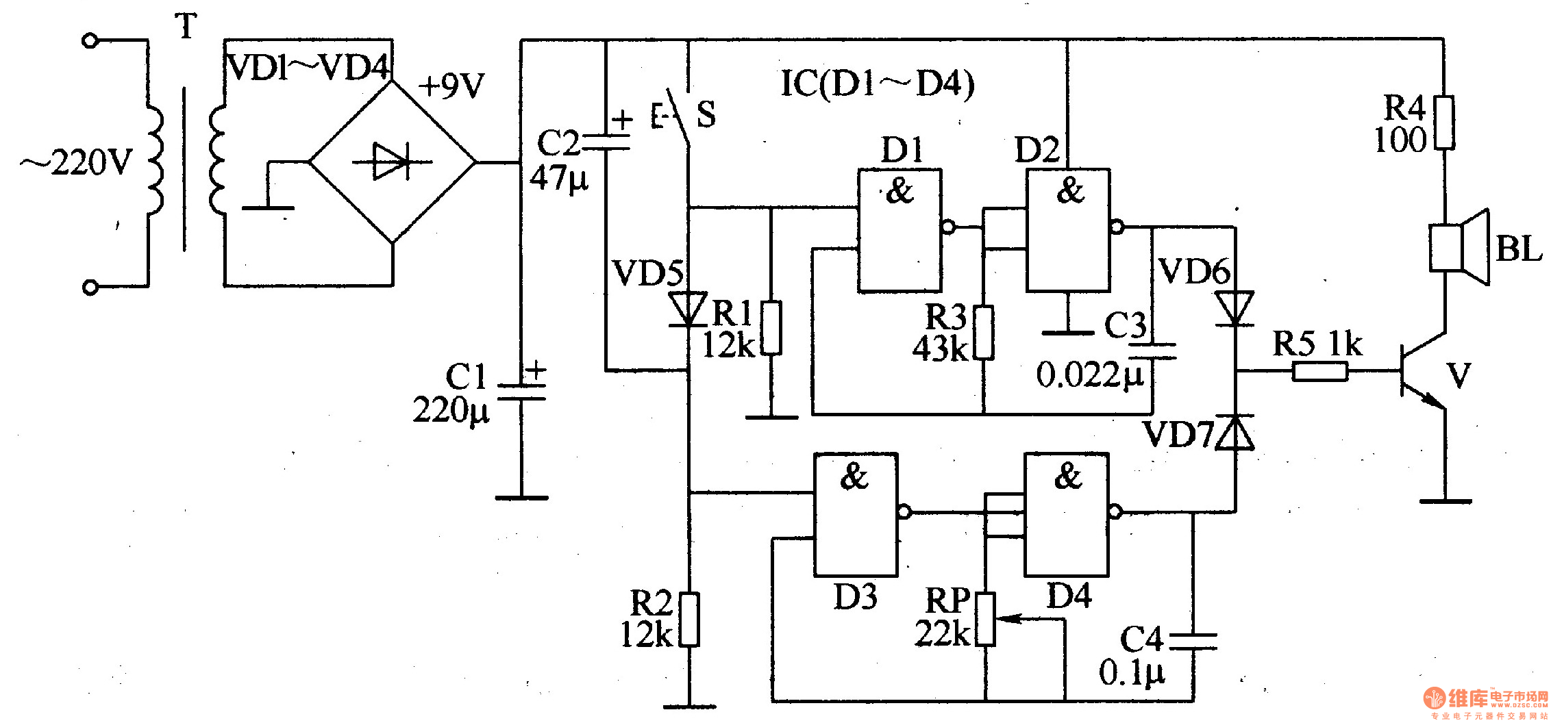
The ding-dong electronic doorbell circuit consists of a power supply circuit, a trigger control circuit, and an audio oscillator output circuit. The power supply circuit includes a power transformer (T), rectifier diodes (VD1-VD4), and a filter capacitor (C1). The...

A circuit breaker is an automatically operated electrical switch designed to protect an electrical circuit from damage caused by overload or short circuit. Its basic function is to detect a fault condition and, by interrupting continuity, immediately discontinue electrical...