
Electronic Thermostat
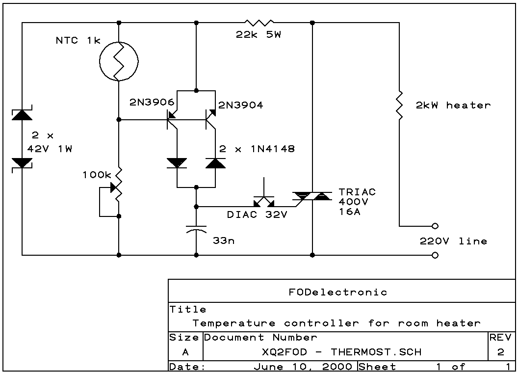
The described circuit is a phase-control mechanism for AC heaters, utilizing a TRIAC and DIAC configuration to modulate the power output effectively. The circuit operates by adjusting the firing angle of the TRIAC, which is crucial for controlling the average power delivered to the heating element. The use of a thermistor as a temperature sensor allows for feedback control, maintaining the desired room temperature within a narrow range.
The circuit begins its operation when a positive half-cycle of the AC voltage is detected. The 22k ohm resistor acts as a current limiter, feeding the necessary voltage to the control circuitry. The upper Zener diode clamps the voltage to 42V, while the lower Zener diode allows current to flow, ensuring that the voltage does not exceed this threshold. The 100k potentiometer is adjusted to provide the correct base-emitter voltage to the PNP transistor, enabling it to conduct when the voltage is sufficiently high.
As the capacitor charges, it accumulates voltage until it reaches approximately 32V. At this point, the DIAC activates, discharging the capacitor into the gate of the TRIAC. Once triggered, the TRIAC remains conducting for the remainder of the half-cycle, effectively powering the heater. The negative half-cycle operates similarly, with the roles of the Zener diodes reversed, allowing the NPN transistor to function in the same manner.
The feedback mechanism involving the thermistor is critical for temperature regulation. As the room temperature increases, the resistance of the thermistor decreases, which in turn reduces the base-emitter voltage of the transistors. This reduction leads to decreased current flow, causing the TRIAC to fire later in the AC cycle, thereby reducing the power output to the heater. In extreme cases, if the temperature rises significantly, the capacitor may not charge sufficiently to trigger the TRIAC, resulting in the heater remaining off.
Thermal management is essential for the reliability of this circuit. The TRIAC can dissipate significant heat due to its voltage drop and the power it controls. It is advisable to employ a heat sink to dissipate this heat effectively, ensuring that the TRIAC operates within safe temperature limits. Proper placement of the thermistor is also necessary to avoid erroneous readings caused by heat generated by other components.
Overall, this circuit design provides a straightforward yet effective means of controlling heater power while maintaining temperature stability, making it suitable for various heating applications.Here is a circuit that implements phase-control of heaters, adjusting their power smoothly from zero to around 95% of the rated power, keeping the room temperature to within 1 or 2 degrees, while using few components. Notice that this is entirely an AC design. The TRIAC, DIAC, capacitor, resistor, potentiometer and thermistor are all AC devices. I did not have a suitable MOV at hand, so I used two Zener diodes in back-to-back fashion. The poorest aspect is that I don't know of the existence of any AC transistors, so I had to pair two complementary ones, joining the collectors through diodes, thus creating my AC transistor from 4 parts!
It works well, but if the transistors are not well matched, this will result in the TRIAC firing earlier in one half cycle than in the other, superposing a DC component on the AC line, which in certain (few) cases can lead to trouble. Try to select nicely matched complimentary transistors! Let's suppose that a positive half-cycle starts. As the voltage rises, the 22k resistor will feed the circuit. The upper Zener diode will clamp the voltage at 42V, with the lower one just conducting. The 100k pot is adjusted in such a way that the base-emitter voltage is just enough to make the PNP transistor conduct.
The capacitor will slowly charge up, reaching 32V sometime within the half cycle. The DIAC will then fire, dumping the capacitor's charge into the TRIAC, which will also fire, and conduct for the rest of the half cycle, keeping the control circuit powered down. For the negative half cycle, everything will be the same, except that the Zeners reverse roles, and the NPN transistor conducts.
The unused transistor in any case stays off, with 0.6V inverse voltage across the base-emitter junction, and its collector insulated by the diode. If the room temperature rises just a little, the resistance of the NTC will drop a little bit. The small reduction in base-emitter voltage will make the transistors conduct dramatically less current, so that the TRIAC will fire much later in the cycle, strongly reducing the heating power.
If the temperature rises enough, for example by sun shining into the window, the capacitor will never charge to 32 V, the TRIAC will never fire, and the heater will stay completely off. On subsequent cycles the capacitor will charge positively and negatively, never accumulating enough voltage to fire the DIAC, eliminating odd-cycle firing, which is a problem in some other designs.
The 22k resistor dissipates more heat as the heater power is reduced, reaching a maximum of about 2W when the heater is fully off. The TRIAC causes about 1.5V drop, so with a 2kW heater it can dissipate almost 15W ! It needs a heat sink. You can bolt it to the metal case of the thermostat, but in this case be sure to follow safety rules.
I suggest using an internally insulated TRIAC. They are easily available. Both the TRIAC and the resistor, and to a much lesser degree the other parts, generate heat that will act upon the thermistor, if you don't take care in placing it properly. While you could install the thermistor remotely, and mount all other parts inside the heater (at a low, cool place!), the long wires between the thermistor and the transistors would lead to RF pickup, and the heater would power up and down erratically in response to radio transmitters, cell phones, etc!
Better keep the thermistor and the rest close together, and mount them in such a way the there can be easy vertical air flow through the case, and that the thermistor is at the lowest spot in the case, with the heat-producing components at the top. At lower temperatures, the transistors will saturate, firing the TRIAC very soon after the waveform reaches the 42 V level.
This affords around 95% of heater power. 🔗 External reference
Related Circuits
This 7-digit combination lock can be easily hard-wired for any combination that you choose. The circuit utilizes a 4-bit, divide-by-8 Johnson counter (IC1), ten push button switches, and an NPN transistor (T1). Upon power-on, capacitor C2 connected to pin...
This circuit illustrates the use of the 4011 integrated circuit (IC) for a surge protection electronic circuit diagram. Features include the ability to delay the activation of other appliances connected to the output. The 4011 IC is a quad 2-input...
The simplicity of a traditional die makes it exceptionally difficult to create a fully equivalent electronic version, primarily because an electronic version necessitates a power supply and a collection of electronic components that occupy a significantly larger volume than...

Metronome is an electronic device that keeps rhythm by making regulated clicking sounds, device used to keep the beat while playing a musical instrument. The circuit is an old design to build, but you will find it useful. The metronome...
Jim Williams possessed a rare ability to combine his diverse talents in science, art, invention, and engineering. He created easily comprehensible tutorials, application notes, and technical phone conversations with customers, which facilitated improved designs in the field of electronics. Jim...
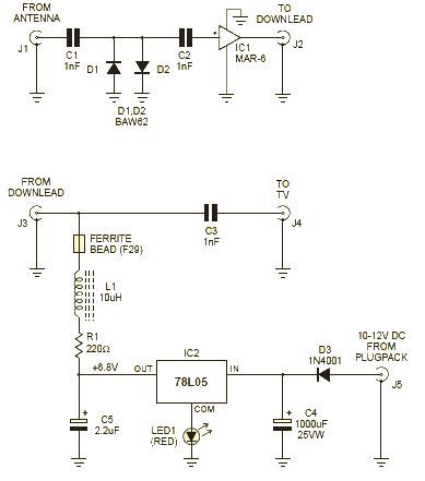
This wideband amplifier circuit is designed using the MAR-6 IC manufactured by Mini Circuits. The MAR-6 VHF-UHF wideband amplifier circuit provides a stable gain of at least 9 dB up to 2 GHz. Since the MAR-6 is designed to...