
Mic condenser amplifier circuit
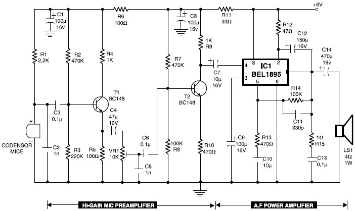
The microphone preamplifier circuit utilizing transistors T1 and T2 is designed to amplify the weak audio signal from a condenser microphone. Resistor R1 is crucial for biasing the microphone, ensuring it operates within its optimal range. The variable resistor VR1 allows for fine-tuning of the gain, enabling users to adjust the output level to suit different input conditions or personal preferences.
The output from this preamplifier stage is connected to an audio power amplifier via coupling capacitor C7. This capacitor serves to block any DC component from the preamplifier, allowing only the AC audio signal to pass through to the amplifier. The audio power amplifier, built around the BEL1895 IC, is capable of delivering up to 0.5 watts of audio power at a supply voltage of 4.5 volts, making it suitable for applications in low-power audio transmission, such as intercoms and walkie-talkies.
The incorporation of a variable frequency oscillator and modulation stages in the circuit further enhances its functionality, allowing for effective short-range communication over the HF band. The use of the BF195 transistor in the transmitter circuit ensures reliable operation across the designated frequency range.
In addition to the microphone preamplifier, the circuit also features a compressor section, which employs transistors to manage the dynamic range of the audio signal. The variable resistors VR1 and VR2 allow for tone adjustments, while VR3 and VR4 are used to strengthen the audio signal, ensuring that the output remains clear and consistent even with varying input levels.
The inclusion of a low-cost hearing aid circuit demonstrates the versatility of this design, as it can be adapted for various applications beyond just audio amplification. The simplicity of the LM358-based microphone preamplifier circuit emphasizes its ease of construction and affordability, making it accessible for hobbyists and professionals alike.
Overall, this comprehensive microphone amplifier circuit design incorporates multiple functionalities, including amplification, tone control, and compression, making it a valuable tool for various audio applications.Transistors T1 and T2 form the mic preamplifier. Resistor R1 gives the required bias for the mic condenser whilst preset VR1 works as gain control for adjusting its gain level. As a way to boost the audio power, the low-level audio output from the preamplifier stage is coupled via coupling capacitor C7 to the audio power amplifier constructed clos
e to BEL1895 IC. This is the circuit diagram of mic condenser amplifier. The low-cost and compact mic condenser audio amplifier described right here is deliver good-quality audio of 0. 5 watts at 4. 5 volts. It could possibly be applied as a part of low-power transmitters, packet radio receivers, intercoms and walkie-talkies.
Transistors T1 and T2 form the mic preamplifier. . Here the SW transmitter circuit based on IC BEL1895. This particular transmitter circuit works in shortwave HF band (6 MHz to 15 MHz), and can be applied for shortrange communication and for educational purposes. The circuit is composed of a mic amplifier circuit, a variable frequency oscillator, and modulation amplifier stages.
Transistor T1 (BF195) is. Below is a mic compressor circuit that uses transistors as active components. VR1 and VR 2 is used to control the tone from the microphone, while VR3 and VR4 strengthening works to control the audio signal in the compressor mic. C10 must be used in this circuit. The circuit I got from my local computer. Here the cheap hearing aid to help people who have hearing loss. Commercially available assistive hearing devices are quite expensive. This is a cheap hearing aid device circuit which works by using just four transistors and several passive electronic components.
On shifting on / off switch S to on` position, the condenser mic detects the. Here the simple audio mic pre amplifier circuit based on single IC LM358. The circuit is very simple, inexpensive and easy to built. Component Parts List: R1, R3, R4 = 10K R2 = 1K R5 = 100K-1M Potensiometer C1 = 0. 1uF C2 = 4. 7uF/16V IC1 = LM358 dual op-amp single supply Mic = Electret Microphone. The circuit below is a Dynamic Mic Compressor circuit is simple but the results are quite satisfactory. Audio output sounded outstanding. The principle of this circuit is very simple, the first transistor is used as Mic Pre-Amp. Then a second transistor used as a buffer. And the third transistor is a feedback circuit. Supply voltage. 🔗 External reference
Related Circuits
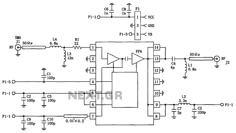
The circuit illustrated in FIG consists of the RF2103P 915MHz RF amplifier circuit. P1 serves as the outlet, where P1-1 connects to power Vcc, P1-2 connects to ground, and P1-3 is used for the power down control voltage VB....
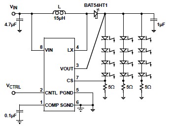
A simple white LED driver schematic can be created using the EL7513 constant current boost regulator, which is specifically designed for driving white LEDs. This driver can manage 4 LEDs in series or up to 12 LEDs in a...
PC parallel port can be very useful I/O channel for connecting your own circuits to PC. The PC's parallel port can be used to perform some very amusing hardware interfacing experiments. The port is very easy to use when...
The test beeper generates a sinusoidal signal with a frequency of 1,000 Hz, which is a standard test frequency for audio amplifiers. It utilizes a Wien-Bridge oscillator configuration, also referred to as a Wien-Robinson oscillator. The frequency-determining network comprises...
The wireless FM transmitter circuit described here includes an additional RF power amplifier stage following the oscillator stage, which increases the power output to 200-250 mW. The wireless FM transmitter circuit functions by modulating audio signals onto a radio frequency...
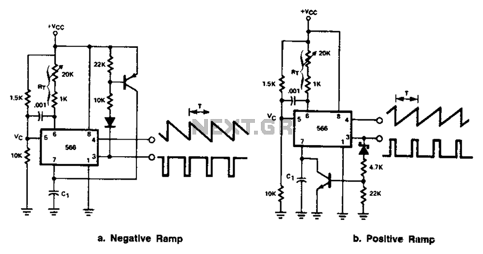
The 566 can be connected to either a positive or negative ramp generator. For a positive ramp generator, an external transistor is driven by the output pin 3. At the end of charging, C1 discharges quickly, allowing for immediate...
Warning: include(partials/cookie-banner.php): Failed to open stream: Permission denied in /var/www/html/nextgr/view-circuit.php on line 713
Warning: include(): Failed opening 'partials/cookie-banner.php' for inclusion (include_path='.:/usr/share/php') in /var/www/html/nextgr/view-circuit.php on line 713