
Electronics Grasshopper using 555
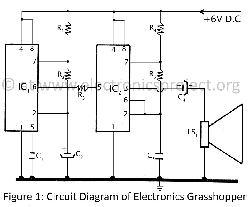
The Electronics Grasshopper project utilizes two NE555 timer ICs configured as astable multivibrators to create an audio output that mimics the sound of insects. The first timer (IC1) operates at a lower frequency and generates a sawtooth waveform, which is essential for modulating the second timer (IC2). The output of IC1 is connected to pin 5 of IC2, which is the control voltage input. This configuration allows IC1 to influence the frequency of IC2's oscillation, effectively creating a variable audio output.
The output from IC2, which operates at a higher frequency, is fed to a speaker via capacitor C4. This capacitor serves to block any DC component from the output, allowing only the AC audio signal to pass through. The resulting sound is a series of high-frequency pulses that can be perceived as a shrill "PI-PI" sound, similar to that of a grasshopper.
Resistors and capacitors in the circuit determine the time intervals for the oscillations of both timers, which can be adjusted to change the pitch and tone of the sound produced. The design is straightforward, making it suitable for educational purposes, as it provides a practical demonstration of oscillators, modulation, and sound generation principles in electronics. This project not only serves as an engaging activity for children but also enhances their understanding of basic electronic components and circuit design.Here is another fun project for children as well as electronics beginners. We often hear the sound of grasshopper or cockroach (i. e. shrill sound) at night. The project published in this website Electronics grasshopper produced PI-PI sound (sound like grasshopper) and can be used as doorbell. The entire circuit of electronics grasshopper is build around pair of timer IC (NE555) followed by few passive component (resistor and capacitor). Both the timer IC (IC1 and IC2) is used here as astable multivibrator. The frequency of IC1 is used to modulate the frequency of IC2 which further given to speaker from pin 3 of IC2 through capacitor C4. The modulation frequency of IC1 is obtained as saw tooth voltage at pin 6 given to control pin 5 of IC2 in order to control frequency of IC2.
IC1 is low frequency oscillator where IC2 is high frequency oscillator. The saw tooth voltage at control pin 5 of IC2 make output audio frequency (3 30 KHz) high and low and listen as shrill sound of insect (pi-pi sound of grasshopper). 🔗 External reference
Related Circuits
This simple battery charger circuit is designed for NiMH/NiCd batteries. It requires no microcontroller or any programming. Linear Technology Corporation. The described battery charger circuit is intended for use with nickel-metal hydride (NiMH) and nickel-cadmium (NiCd) batteries, which are commonly...

There are many posts on Instructables detailing how to create a flickering LED candle. This version of the project requires several components. The flickering LED candle project aims to simulate the warm glow and flicker of a real candle using...

Figure 2-33 (a) illustrates the schematic diagram of a robot approaching an object. When no objects are detected in front of the robot, it moves forward in a straight line. If an object is detected on the left or...
There are numerous LED flasher projects available on the internet, some of which are designed for low current consumption. However, the requirement was for an extremely small flasher suitable for geocaching that could last at least one year using...

A water level controller based on the 8051 microcontroller is presented in this article. While numerous water level controller projects have been published on this website, this is the first one utilizing a microcontroller. The water level controller monitors...
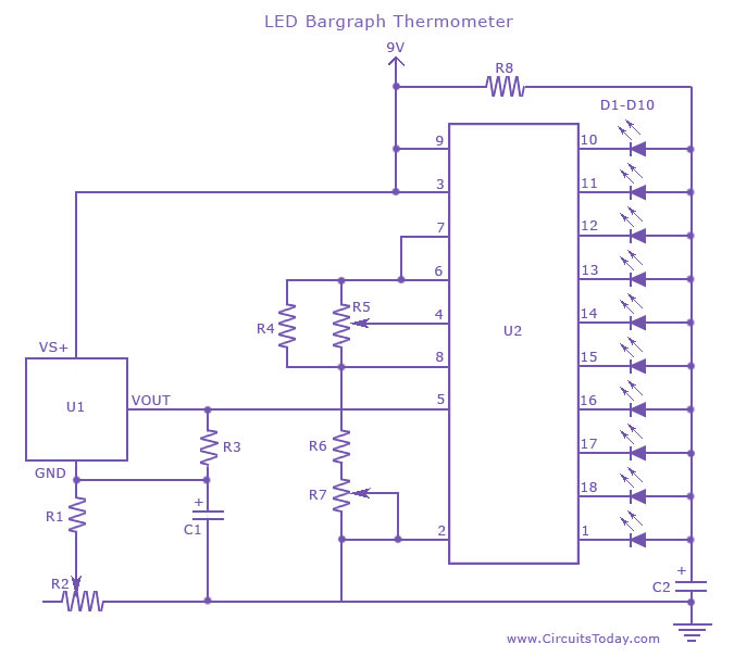
An LED thermometer that can function as a temperature sensor or temperature measurement circuit, utilizing the LM34 for Fahrenheit display or the LM35 for degree Celsius display. The LED thermometer circuit is designed to provide accurate temperature readings using either...